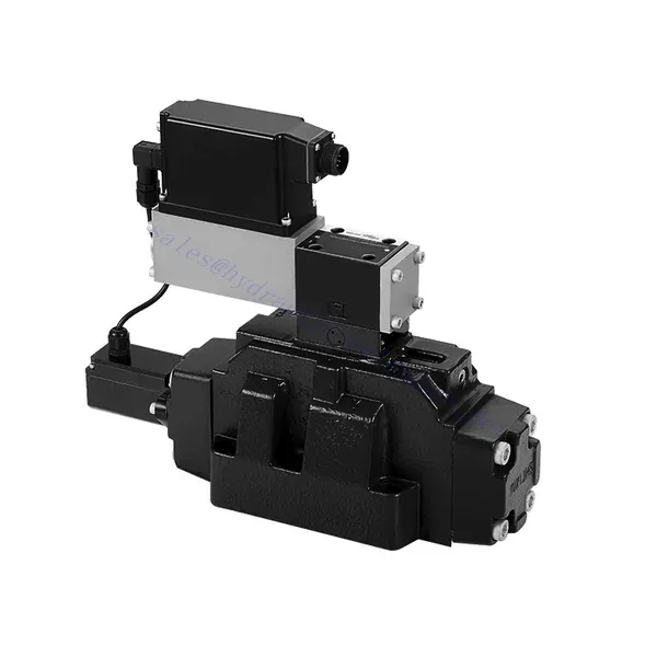
4WRLE 시리즈 파일럿 작동 비례 방향 유압 밸브
유압 실린더 제조업체, 공급 업체 및 기계 제품 수출 업체 중 하나로서 유압 실린더 및 기타 여러 제품을 제공합니다.
자세한 내용은 당사에 문의해 주세요.
메일:sales@hydraulic-cylinders.net
유압 실린더 제조업체 공급 업체 수출.
4WRLE 시리즈 파일럿 작동 비례 방향 유압 밸브
The 4WRLE series pilot-operated proportional directional hydraulic valve is a cutting-edge hydraulic component that revolutionizes fluid control in hydraulic systems. This valve combines pilot-operated technology with proportional directional control, offering precise flow regulation and exceptional efficiency.
The 4WRLE series pilot-operated proportional directional hydraulic valve elevates hydraulic control to new heights of precision and efficiency. With its pilot-operated technology and proportional directional control, this valve ensures accurate flow regulation, optimized energy consumption, and enhanced system performance. By following the recommended usage methods and maintenance guidelines, you can unleash the full potential of the 4WRLE series valve and achieve superior hydraulic control. Upgrade your hydraulic system today and experience the power of precision with the 4WRLE series pilot-operated proportional directional hydraulic valve.
4WRLE Series Pilot Operated Proportional Directional Hydraulic Valve Key Characteristics:
- Pilot Operated Technology:
- The 4WRLE series valve incorporates pilot-operated technology, allowing precise fluid flow control and pressure regulation.
- This technology enables efficient energy usage and reduces heat generation, resulting in improved overall system performance and reduced operating costs.
- Proportional Directional Control:
- With its proportional directional control capability, this valve provides accurate and balanced flow adjustment based on control signals.
- The proportional control allows for smooth and precise control of hydraulic actuators, enhancing system performance and minimizing wear and tear.
- 다양한 기능:
- The 4WRLE series valve offers versatile control over fluid direction, making it suitable for a wide range of hydraulic applications.
- Whether it’s controlling cylinders, motors, or other hydraulic components, this valve ensures seamless activation and deactivation in different directions, enhancing system flexibility and adaptability.
- 고유량 용량:
- Designed to handle high flow rates, the 4WRLE series valve delivers exceptional performance even in demanding applications.
- Its robust construction and optimized flow channels ensure reliable operation and consistent flow control, meeting the requirements of high-power hydraulic systems.
4WRLE Series Pilot Operated Proportional Directional Hydraulic Valve Parameter:
NG6
| 일반적인 | |||||||
| 설계 | Spool valve, direct operated, with steel sleeve | ||||||
| 작동 | Proportional solenoid with position control, OBE | ||||||
| 연결 유형 | Subplate mounting, porting pattern according to ISO 4401-03-02-0-05 | ||||||
| 설치 위치 | Any | ||||||
| 주변 온도 범위 | ℃ | -20…+50 | |||||
| 무게 | 킬로그램 | about 2.75 | |||||
| Maximum vibration resistance (test condition) | Max. 25 g, space vibration test in all directions (24h) | ||||||
| 유압 (measured at p=100bar, with HLP46 at ϑoil = 40℃ ±5℃) | |||||||
| 압력 유체 | Mineral oil (HL, HLP)to DIN 51 524 | ||||||
| 점도 범위 | 추천 | mm²/초 | 20…100 | ||||
| 최대 허용 | mm²/초 | 10…800 | |||||
| 압력 유체 온도 범위 | ℃ | -20 to +70 | |||||
| Maximum permitted degree of contamination of pressure fluid Purity class to ISO 4406 (c) | 2013년 18월 16일 수업 | ||||||
| Rated flow (Δp = 35 bar per edge) | 리터/분 | 2 | 4 | 12 | 24 | 40 | |
| 최대 작동 압력 | 술집 | Port A、B、P:315 | |||||
| 최대 압력 | 술집 | 포트 T: 250 | |||||
| Leakage flow at 100 bar | Linear | cm³/min | <150 | <180 | <300 | <500 | <900; |
| Nonlinear | cm³/min | / | / | / | <300 | <450; | |
| 정적/동적 | |||||||
| 히스테리시스 | % | ≤0.2 | |||||
| Actuating time for signal step 0 … 100% | 미시시피 | 10 | |||||
| Temperature drift | Zero shift < 1% at ΔT=40℃ | ||||||
| Zero compensation | Ex factory ±1% | ||||||
| Electric, control electronics integrated in the valve | |||||||
| Relative duty cycle | % | 100ED | |||||
| 보호 정도 | IP65 | ||||||
| 연결 | Plug-in connector 6P+PE, DIN 43563 | ||||||
| Supply voltage Terminal A Terminal B |
24VDCnom | ||||||
| min. 21VDC / max. 40VDC | |||||||
| 0V (ripple max. 2) | |||||||
| Fuse protection, external | AF | 2.5 | |||||
| nput, version “A1” Terminal D (UE) Terminal E |
Differential amplifier, Ri = 100 kΩ | ||||||
| 0…±10V | |||||||
| 0V | |||||||
| Input, version “F1” Terminal D (ID-E) Terminal E (ID-E) |
Load, Rsh = 200 Ω | ||||||
| 4…12…20mA | |||||||
| Current loop ID-E return | |||||||
| Test signal, version “A1” Terminal F (UTest) Terminal C |
LVDT | ||||||
| 0…±10V | |||||||
| Reference 0 V | |||||||
| Test signal, version “F1” Terminal F ( I F-C ) Terminal C ( I F-C ) |
LVDT signal 4 … (12) … 20 mA on external load 200 … 500 Ωmaximum | ||||||
| 4 … (12) … 20mA (output) | |||||||
| Current loop IF-C return | |||||||
| Adjustment | Calibrated before delivery, see characteristic curves | ||||||
NG10
| 일반적인 | |||||
| 설계 | Spool valve, directly operated, with steel sleeve | ||||
| 작동 | Proportional solenoid with position control, OBE | ||||
| 연결 유형 | Plate port, porting pattern (ISO 4401-05-04-0-05) | ||||
| 설치 위치 | Any | ||||
| 상황 온도 범위 | ℃ | -20…+50 | |||
| 무게 | 킬로그램 | about 7.1 | |||
| Maximum vibration resistance (test condition) | Max. 25 g, space vibration test in all directions (24h) | ||||
| Hydraulic (measured with HLP 46, ϑoil =40℃ ±5℃) | |||||
| 압력 유체 | Hydraulic oil according to DIN 51524…535 | ||||
| 점도 범위 | 추천 | mm²/초 | 20…100 | ||
| Max. permitted | mm²/초 | 10…800 | |||
| 압력 유체 온도 범위 | ℃ | -20 to +70 | |||
| Max. admissible degree of contamination of the hydraulic fluid,cleanliness class according to ISO 4406 (c) | 2013년 18월 16일 수업 | ||||
| Rated flow(Δp = 35 bar per edge) | 리터/분 | 50 | 100 | ||
| 최대 작동 압력 | 술집 | Port P A B: 315 | |||
| 최대 압력 | 술집 | 포트 T: 250 | |||
| Leakage flow at 100 bar | Linear | cm³/min | <1200 | <1500 | |
| Nonlinear | cm³/min | <600 | <600 | ||
| 정적/동적 | |||||
| 히스테리시스 | % | ≤0.2 | |||
| Actuating time for signal step 0 … 100% | 미시시피 | 25 | |||
| Temperature drift | Zero shift < 1% at ΔT=40℃ | ||||
| Zero compensation | Ex factory ±1% | ||||
| Electric, control electronics integrated in the valve | |||||
| Relative duty cycle | % | 100ED | |||
| 보호 정도 | IP65(with mating connector mounted and locked ) | ||||
| 연결 | Mating connector 6P+PE, DIN 43563 | ||||
| Supply voltage Terminal A Terminal B |
24VDCnom | ||||
| min. 21VDC / max. 40VDC | |||||
| Ripple max. 2 VDC | |||||
| Fuse protection, external | AF | 2.5 | |||
| Input, version “A1” Terminal D (UE) Terminal E |
Differential amplifier, Ri = 100 kΩ | ||||
| 0…±10V | |||||
| 0V | |||||
| Input, version “F1” Terminal D (ID-E) Terminal E (ID-E) |
Load, Rsh = 200 | ||||
| 4…12…20mA | |||||
| Current loop ID-E return | |||||
| Test signal, version “A1” Terminal F (U시험) Terminal C |
LVDT | ||||
| 0…±10V | |||||
| Reference 0 V | |||||
| Test signal, version “F1” Terminal F ( I F-C ) Terminal C ( I F-C ) |
LVDT | ||||
| 4…20 mA output | |||||
| Current loop IF-C feedback | |||||
4WRLE Series Pilot Operated Proportional Directional Hydraulic Valve Advantages:
• Direct-acting servo solenoid valve with control piston and valve sleeve, with servo performance
• Single-side drive, optional, with power-off safety function
Control solenoid with built-in feedback and integrated amplifier board (OBE), factory preset
• Electrical connection 6P+PE signal input differential amplifier with interface, input optional A1: ±10V, or interface F1: 4…20mA (Rsh =200Ω)
• Panel mounting: the mounting surface complies with ISO 4401-03-02
Usage Method Of 4WRLE Series Pilot Operated Proportional Directional Hydraulic Valve:
- 시스템 평가:
- Evaluate your hydraulic system and define the specific flow and directional control requirements.
- Identify whether the 4WRLE series valve is compatible with your system based on factors such as flow capacity, pressure rating, and compatibility with your application.
- 밸브 선택:
- Select the appropriate variant of the 4WRLE series valve based on your system parameters, flow requirements, and directional control needs.
- Consider factors such as maximum flow rate, pressure rating, response time, and environmental operating conditions.
- 설치:
- 적절한 정렬과 안전한 밸브 장착을 위해 제조업체의 설치 지침을 주의 깊게 따르세요.
- Create leak-free connections and ensure correct flow direction alignment to guarantee optimal performance.
- Control Signal Integration:
- 밸브의 제어 신호선을 비례 증폭기나 전자 제어 장치와 같은 적절한 제어 장치에 연결합니다.
- Ensure proper wiring and compatibility between the valve and control device to achieve accurate and responsive control.
유압 유량 제어 밸브를 연결하는 방법은?
유압 유량 제어 밸브를 연결하려면 다음 단계를 따르세요.
- 밸브 유형 식별: 작업 중인 유량 제어 밸브의 구체적인 유형을 확인하십시오. 일반적인 유형으로는 니들 밸브, 조절식 유량 제어 밸브, 압력 보상식 유량 제어 밸브 등이 있습니다. 밸브가 해당 용도에 적합하고 유압 시스템과 호환되는지 확인하십시오.
- 필요한 도구와 재료를 모으세요: 적절한 유압 피팅, 어댑터, 호스, 렌치 등 필요한 도구와 재료를 모으세요.
- 유압 시스템 준비: 유압 시스템을 정지하고 릴리프 밸브를 작동하거나 유압 실린더를 수축시켜 시스템 내 압력을 제거하십시오. 이 단계는 안전을 위해 매우 중요합니다.
- 흐름 방향 식별: 유압 시스템의 흐름 방향을 확인하십시오. 일반적으로 흐름 방향은 유압 부품에 화살표로 표시됩니다. 작업을 진행하기 전에 올바른 흐름 방향을 확인하십시오.
- 설치 지점 찾기: 유압 시스템에 유량 제어 밸브를 설치할 최적의 위치를 결정하십시오. 접근성, 액추에이터 또는 유압 부품과의 근접성, 조정 용이성 등의 요소를 고려하십시오.
- 밸브 장착: 적절한 브래킷이나 클램프를 사용하여 유량 제어 밸브를 선택한 위치에 단단히 장착하십시오. 밸브가 올바른 위치에 있는지 확인하고, 입구와 출구 포트를 흐름 방향에 맞춰 정렬하십시오.
- 입구 및 출구 포트를 연결합니다. 유량 제어 밸브의 입구 및 출구 포트에 유압 호스나 튜빙을 연결하십시오. 누출 없이 연결하려면 적합한 유압 피팅과 어댑터를 사용하십시오. 렌치를 사용하여 연결부를 조여 단단히 고정하되, 너무 세게 조이지 마십시오.
- 흐름 제어 조정: 유량 제어 밸브의 종류에 따라 니들 밸브나 유량 조절 손잡이와 같은 조절 기능이 있을 수 있습니다. 원하는 유량이나 속도에 따라 밸브를 조절하십시오. 구체적인 조절 절차는 제조업체의 지침을 참조하십시오.
- 시스템 테스트: 유량 제어 밸브를 설치하고 조정한 후 유압 시스템 압력을 천천히 회복하십시오. 유량 제어 밸브가 제대로 작동하는지 시스템을 테스트하십시오. 유압 액추에이터의 유량 또는 속도를 모니터링하여 원하는 범위 내에 있는지 확인하십시오.
- 미세 조정 및 모니터링: 원하는 유량이나 속도를 얻으려면 유량 제어 밸브를 조정하십시오. 유압 시스템의 누출, 압력 불균형 또는 이상 작동 여부를 정기적으로 모니터링하십시오.
공장의 역량 및 용량:
(1) 조립
당사는 최고 수준의 독자적인 연구개발 조립 플랫폼을 보유하고 있습니다. 유압 실린더 생산 작업장은 4개의 반자동 리프팅 실린더 조립 라인과 1개의 자동 틸트 실린더 조립 라인을 갖추고 있으며, 연간 100만 개의 설계 생산 능력을 갖추고 있습니다. 특수 실린더 작업장은 다양한 사양의 반자동 세척 조립 시스템을 갖추고 있으며, 연간 20만 개의 설계 생산 능력을 갖추고 있습니다. 또한, 유명 CNC 가공 장비, 머시닝 센터, 고정밀 실린더 가공 특수 장비, 로봇 용접기, 자동 세척기, 자동 실린더 조립기, 자동 도장 생산 라인을 갖추고 있습니다. 300대 이상의 핵심 장비를 보유하고 있으며, 장비 자원의 최적 배치 및 효율적인 사용을 통해 제품의 정밀성 요구 사항을 충족하고 고품질 요구를 충족합니다.


(2) 가공
가공공장은 맞춤형 경사레일 터닝센터, 가공센터, 고속 호닝머신, 용접로봇 및 기타 관련 장비를 갖추고 있으며, 최대 내경 400mm, 최대 길이 6m의 원통형 튜브를 가공할 수 있습니다.

(3) 용접

(4) 도장 및 코팅
소형, 중형 실린더 자동 수성 페인트 코팅 라인을 통해 자동 로봇 로딩 및 언로딩과 자동 분무를 실현하며, 교대당 4000개의 설계 용량을 달성합니다.
또한, 우리는 60개의 케이스를 교대로 생산할 수 있는 설계 용량을 갖춘 파워 체인으로 구동되는 대형 실린더용 반자동 페인트 생산 라인을 보유하고 있습니다.


(5) 테스트
당사는 실린더의 성능이 요구 사항을 충족하는지 확인하기 위해 일류 검사 시설과 테스트 베드를 갖추고 있습니다.

저희는 최고의 유압 실린더 제조업체 중 하나입니다. 다양한 유압 실린더를 공급할 수 있으며, 관련 제품도 제공합니다. 농업용 기어박스저희는 전 세계 고객에게 제품을 수출해 왔으며, 탁월한 제품 품질과 애프터서비스를 통해 좋은 평판을 얻고 있습니다. 국내외 고객 여러분의 사업 상담, 정보 교환, 그리고 우리와 협력하다!
유압 실린더 응용 분야:
