
4WRPEH 시리즈 비례 방향 유압 밸브
유압 실린더 제조업체, 공급 업체 및 기계 제품 수출 업체 중 하나로서 유압 실린더 및 기타 여러 제품을 제공합니다.
자세한 내용은 당사에 문의해 주세요.
메일:sales@hydraulic-cylinders.net
유압 실린더 제조업체 공급 업체 수출.
4WRPEH 시리즈 비례 방향 유압 밸브
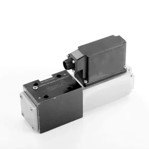
The 4WRPEH series proportional directional hydraulic valve is an advanced hydraulic component designed to deliver exceptional precision and control in hydraulic systems. With its innovative proportional directional control technology, this valve enables accurate flow regulation and smooth directional changes.
The 4WRPEH series proportional directional hydraulic valve empowers hydraulic systems with precise flow control, versatile functionality, and enhanced efficiency. Its proportional directional control technology ensures accurate and responsive flow adjustment, while the high flow capacity guarantees reliable performance even in demanding applications. By following the recommended usage methods and maintenance guidelines, you can maximize the benefits and longevity of the 4WRPEH series valve, elevating your hydraulic system to new levels of precision and control. Upgrade your hydraulic setup today and experience the power of the 4WRPEH series proportional directional hydraulic valve.
4WRPEH Series Proportional Directional Hydraulic Valve Key Characteristics:
- Proportional Directional Control:
- The 4WRPEH series valve utilizes state-of-the-art proportional directional control technology, allowing precise and proportional flow adjustment based on control signals.
- 이 기능은 정확하고 반응성이 뛰어난 제어를 보장하여 시스템 성능을 개선하고, 에너지 소비를 줄이며, 생산성을 향상시킵니다.
- 다양한 기능:
- 이 밸브는 유압 유체 방향에 대한 다양한 제어 기능을 제공하므로 광범위한 응용 분야에 적합합니다.
- 실린더, 모터, 액추에이터 등의 유압 구성 요소를 다양한 방향으로 원활하게 활성화 및 비활성화할 수 있어 시스템의 유연성과 적응성이 향상됩니다.
- 고유량 용량:
- The 4WRPEH series valve is engineered to handle high flow rates, making it ideal for applications that require substantial hydraulic power.
- 견고한 구조로 까다로운 조건에서도 안정적인 성능을 보장하며, 일관되고 효율적인 흐름 제어를 제공합니다.
- Precise Metering:
- With its proportional control technology, this valve offers precise metering of hydraulic fluid, allowing for accurate control and regulation of flow rates.
- This precision enhances overall system performance and ensures precise movements of hydraulic actuators.
4WRPEH Series Proportional Directional Hydraulic Valve Parameter:
NG6
| 일반적인 | |||||||
| 설계 | Spool valve, direct operated, with steel sleeve | ||||||
| 작동 | Proportional solenoid with position control, OBE | ||||||
| 연결 유형 | Subplate mounting, porting pattern according to ISO 4401-03-02-0-05 | ||||||
| 설치 위치 | Any | ||||||
| 주변 온도 범위 | ℃ | -20…+50 | |||||
| 무게 | 킬로그램 | about 2.75 | |||||
| Maximum vibration resistance (test condition) | Max. 25 g, space vibration test in all directions (24h) | ||||||
| 유압 (measured at p=100bar, with HLP46 at ϑoil = 40℃ ±5℃) | |||||||
| 압력 유체 | Mineral oil (HL, HLP)to DIN 51 524 | ||||||
| 점도 범위 | 추천 | mm²/초 | 20…100 | ||||
| 최대 허용 | mm²/초 | 10…800 | |||||
| 압력 유체 온도 범위 | ℃ | -20 to +70 | |||||
| Maximum permitted degree of contamination of pressure fluid Purity class to ISO 4406 (c) | 2013년 18월 16일 수업 | ||||||
| Rated flow (Δp = 35 bar per edge) | 리터/분 | 2 | 4 | 12 | 24 | 40 | |
| 최대 작동 압력 | 술집 | Port A、B、P:315 | |||||
| 최대 압력 | 술집 | 포트 T: 250 | |||||
| Leakage flow at 100 bar | Linear | cm³/min | <150 | <180 | <300 | <500 | <900; |
| Nonlinear | cm³/min | / | / | / | <300 | <450; | |
| 정적/동적 | |||||||
| 히스테리시스 | % | ≤0.2 | |||||
| Actuating time for signal step 0 … 100% | 미시시피 | 10 | |||||
| Temperature drift | Zero shift < 1% at ΔT=40℃ | ||||||
| Zero compensation | Ex factory ±1% | ||||||
| Electric, control electronics integrated in the valve | |||||||
| Relative duty cycle | % | 100ED | |||||
| 보호 정도 | IP65 | ||||||
| 연결 | Plug-in connector 6P+PE, DIN 43563 | ||||||
| Supply voltage Terminal A Terminal B |
24VDCnom | ||||||
| min. 21VDC / max. 40VDC | |||||||
| 0V (ripple max. 2) | |||||||
| Fuse protection, external | AF | 2.5 | |||||
| nput, version “A1” Terminal D (UE) Terminal E |
Differential amplifier, Ri = 100 kΩ | ||||||
| 0…±10V | |||||||
| 0V | |||||||
| Input, version “F1” Terminal D (ID-E) Terminal E (ID-E) |
Load, Rsh = 200 Ω | ||||||
| 4…12…20mA | |||||||
| Current loop ID-E return | |||||||
| Test signal, version “A1” Terminal F (UTest) Terminal C |
LVDT | ||||||
| 0…±10V | |||||||
| Reference 0 V | |||||||
| Test signal, version “F1” Terminal F ( I F-C ) Terminal C ( I F-C ) |
LVDT signal 4 … (12) … 20 mA on external load 200 … 500 Ωmaximum | ||||||
| 4 … (12) … 20mA (output) | |||||||
| Current loop IF-C return | |||||||
| Adjustment | Calibrated before delivery, see characteristic curves | ||||||
NG10
| 일반적인 | |||||
| 설계 | Spool valve, directly operated, with steel sleeve | ||||
| 작동 | Proportional solenoid with position control, OBE | ||||
| 연결 유형 | Plate port, porting pattern (ISO 4401-05-04-0-05) | ||||
| 설치 위치 | Any | ||||
| 상황 온도 범위 | ℃ | -20…+50 | |||
| 무게 | 킬로그램 | about 7.1 | |||
| Maximum vibration resistance (test condition) | Max. 25 g, space vibration test in all directions (24h) | ||||
| Hydraulic (measured with HLP 46, ϑoil =40℃ ±5℃) | |||||
| 압력 유체 | Hydraulic oil according to DIN 51524…535 | ||||
| 점도 범위 | 추천 | mm²/초 | 20…100 | ||
| Max. permitted | mm²/초 | 10…800 | |||
| 압력 유체 온도 범위 | ℃ | -20 to +70 | |||
| Max. admissible degree of contamination of the hydraulic fluid,cleanliness class according to ISO 4406 (c) | 2013년 18월 16일 수업 | ||||
| Rated flow(Δp = 35 bar per edge) | 리터/분 | 50 | 100 | ||
| 최대 작동 압력 | 술집 | Port P A B: 315 | |||
| 최대 압력 | 술집 | 포트 T: 250 | |||
| Leakage flow at 100 bar | Linear | cm³/min | <1200 | <1500 | |
| Nonlinear | cm³/min | <600 | <600 | ||
| 정적/동적 | |||||
| 히스테리시스 | % | ≤0.2 | |||
| Actuating time for signal step 0 … 100% | 미시시피 | 25 | |||
| Temperature drift | Zero shift < 1% at ΔT=40℃ | ||||
| Zero compensation | Ex factory ±1% | ||||
| Electric, control electronics integrated in the valve | |||||
| Relative duty cycle | % | 100ED | |||
| 보호 정도 | IP65(with mating connector mounted and locked ) | ||||
| 연결 | Mating connector 6P+PE, DIN 43563 | ||||
| Supply voltage Terminal A Terminal B |
24VDCnom | ||||
| min. 21VDC / max. 40VDC | |||||
| Ripple max. 2 VDC | |||||
| Fuse protection, external | AF | 2.5 | |||
| Input, version “A1” Terminal D (UE) Terminal E |
Differential amplifier, Ri = 100 kΩ | ||||
| 0…±10V | |||||
| 0V | |||||
| Input, version “F1” Terminal D (ID-E) Terminal E (ID-E) |
Load, Rsh = 200 | ||||
| 4…12…20mA | |||||
| Current loop ID-E return | |||||
| Test signal, version “A1” Terminal F (U시험) Terminal C |
LVDT | ||||
| 0…±10V | |||||
| Reference 0 V | |||||
| Test signal, version “F1” Terminal F ( I F-C ) Terminal C ( I F-C ) |
LVDT | ||||
| 4…20 mA output | |||||
| Current loop IF-C feedback | |||||
4WRPEH Series Proportional Directional Hydraulic Valve Advantages:
• Direct-acting servo solenoid valve with control piston and valve sleeve, with servo performance
• Single-side drive, optional with power-off safety function
Control solenoid with built-in feedback and integrated amplifier board (OBE), factory preset
• Electrical connection 6P+PE signal input differential amplifier with interface, input optional A1: ±10V, or interface F1: 4…20mA (Rsh =200Ω)
• Panel mounting, the mounting surface complies with ISO 4401-03-02
Usage Method Of 4WRPEH Series Proportional Directional Hydraulic Valve :
- 시스템 평가:
- 유압 시스템을 평가하고 특정 흐름 및 방향 제어 요구 사항을 파악합니다.
- Determine if the 4WRPEH series valve is suitable based on its flow capacity, pressure rating, and compatibility with your system.
- 밸브 선택:
- Select the appropriate variant of the 4WRPEH series valve based on your system parameters, flow requirements, and directional control needs.
- 최대 유량, 압력 등급, 응답 시간, 작동 조건 등의 요소를 고려하세요.
- 설치:
- 제조업체의 설치 지침을 주의 깊게 따르고 밸브가 올바르게 정렬되고 안전하게 장착되도록 하세요.
- Make leak-free connections and ensure correct flow direction alignment to guarantee optimal performance.
- 제어 신호 연결:
- 밸브의 제어 신호선을 비례 증폭기나 전자 제어 장치와 같은 적절한 제어 장치에 연결합니다.
- 정확하고 반응성 있는 제어를 위해 밸브와 제어 장치 간의 적절한 배선과 호환성을 확보하세요.
How To Hook Two Hydraulic Valves Together?
Hooking two hydraulic valves together requires careful consideration of the valve types, their functions, and the specific hydraulic system requirements. Here are general guidelines on how to hook two hydraulic valves together:
- Identify Valve Types:
- Determine the types of valves you are working with, such as directional control valves, pressure control valves, flow control valves, or any other specific valves required for your system.
- Ensure that both valves are compatible in terms of size, pressure ratings, flow capacity, and function.
- Understand Valve Functions:
- Familiarize yourself with the functions of each valve. For example, directional control valves regulate fluid flow direction, pressure control valves control system pressure, and flow control valves manage flow rates.
- Determine how the combination of these valves will contribute to achieving the desired hydraulic system operation.
- Determine Valve Placement:
- Decide where in the hydraulic system you want to install the two valves. Consider factors such as fluid flow path, pressure requirements, and the desired control sequence.
- Ensure that the valve placement allows for proper fluid flow and accessibility for maintenance and operation.
- Connect Valve Ports:
- Identify the inlet and outlet ports of each valve. These ports may be labeled or indicated in the valve documentation.
- Use appropriate hydraulic fittings, adapters, or connectors to connect the ports of the two valves together.
- Ensure a secure and leak-free connection by using suitable sealing materials, such as O-rings or thread sealants.
- Consider Valve Interactions:
- Evaluate how the interaction between the two valves will affect the hydraulic system’s overall performance.
- Ensure that the combined operation of the valves does not create conflicts or result in unintended consequences, such as pressure spikes, flow restrictions, or unintended movements.
- Control Signal Integration:
- If the valves require control signals, such as electrical or pneumatic signals, determine how these signals will be integrated.
- Connect the control signal lines of both valves to the appropriate control devices, such as hydraulic control modules, electronic control units, or manual control levers.
- Ensure proper wiring, compatibility, and synchronization between the control devices and the valves to achieve the desired control and coordination.
- Test and Adjust:
- After hooking the valves together, thoroughly test the hydraulic system to ensure proper operation.
- Monitor the system for any issues, such as leaks, excessive pressure drops, or unexpected behavior.
- Make necessary adjustments, such as fine-tuning control settings or modifying valve placement if required.
공장의 역량 및 용량:
(1) 조립
당사는 최고 수준의 독자적인 연구개발 조립 플랫폼을 보유하고 있습니다. 유압 실린더 생산 작업장은 4개의 반자동 리프팅 실린더 조립 라인과 1개의 자동 틸트 실린더 조립 라인을 갖추고 있으며, 연간 100만 개의 설계 생산 능력을 갖추고 있습니다. 특수 실린더 작업장은 다양한 사양의 반자동 세척 조립 시스템을 갖추고 있으며, 연간 20만 개의 설계 생산 능력을 갖추고 있습니다. 또한, 유명 CNC 가공 장비, 머시닝 센터, 고정밀 실린더 가공 특수 장비, 로봇 용접기, 자동 세척기, 자동 실린더 조립기, 자동 도장 생산 라인을 갖추고 있습니다. 300대 이상의 핵심 장비를 보유하고 있으며, 장비 자원의 최적 배치 및 효율적인 사용을 통해 제품의 정밀성 요구 사항을 충족하고 고품질 요구를 충족합니다.


(2) 가공
가공공장은 맞춤형 경사레일 터닝센터, 가공센터, 고속 호닝머신, 용접로봇 및 기타 관련 장비를 갖추고 있으며, 최대 내경 400mm, 최대 길이 6m의 원통형 튜브를 가공할 수 있습니다.

(3) 용접

(4) 도장 및 코팅
소형, 중형 실린더 자동 수성 페인트 코팅 라인을 통해 자동 로봇 로딩 및 언로딩과 자동 분무를 실현하며, 교대당 4000개의 설계 용량을 달성합니다.
또한, 우리는 60개의 케이스를 교대로 생산할 수 있는 설계 용량을 갖춘 파워 체인으로 구동되는 대형 실린더용 반자동 페인트 생산 라인을 보유하고 있습니다.


(5) 테스트
당사는 실린더의 성능이 요구 사항을 충족하는지 확인하기 위해 일류 검사 시설과 테스트 베드를 갖추고 있습니다.

저희는 최고의 유압 실린더 제조업체 중 하나입니다. 다양한 유압 실린더를 공급할 수 있으며, 관련 제품도 제공합니다. 농업용 기어박스저희는 전 세계 고객에게 제품을 수출해 왔으며, 탁월한 제품 품질과 애프터서비스를 통해 좋은 평판을 얻고 있습니다. 국내외 고객 여러분의 사업 상담, 정보 교환, 그리고 우리와 협력하다!
유압 실린더 응용 분야:
