리프팅 플랫폼용 방폭형 유압 시스템
유압 실린더 제조업체, 공급 업체 및 기계 제품 수출 업체 중 하나로서 유압 실린더 및 기타 여러 제품을 제공합니다.
자세한 내용은 당사에 문의해 주세요.
메일:sales@hydraulic-cylinders.net
유압 실린더 제조업체 공급 업체 수출.
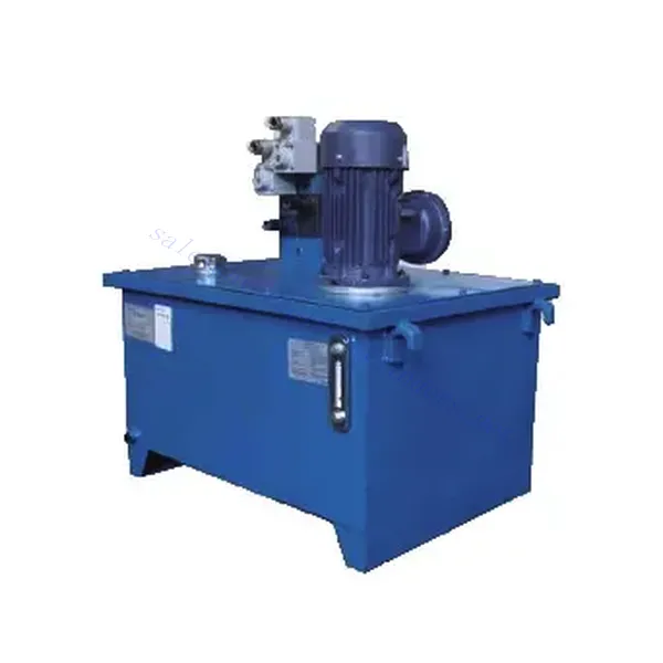
리프팅 플랫폼용 방폭형 유압 시스템

Explosion-proof hydraulic systems for lifting platforms are a state-of-the-art solution designed to provide safe and reliable vertical mobility in hazardous environments with a risk of explosion or flammable substances. This specialized hydraulic system ensures optimal performance while prioritizing operator and equipment safety. Below, we will discuss the main characteristics of the lifting platform explosion-proof hydraulic system, methods, maintenance, and other vital aspects.
리프터용 유압 시스템 매개변수:
Motor Power:1.5KW
Oil Tank:150L
Characteristics of the Explosion-Proof Hydraulic System For Lifting Platform:
- Compliance with Safety Standards:
- Certified Explosion-Proof Components: The hydraulic system has explosion-proof components that meet stringent safety standards, ensuring reliable operation in hazardous environments.
- Classifications and Ratings: The system adheres to defined types and ratings, such as ATEX or IECEx, to ensure compliance with industry-specific regulations for explosion protection.
- 견고한 구조:
- Durable Materials: The system uses high-quality, durable materials that withstand harsh operating conditions, including exposure to flammable gases, vapors, or dust.
- Reinforced Sealing: Special sealing mechanisms and gaskets are employed to prevent the ingress of hazardous substances into the hydraulic system, maintaining the integrity of the equipment.
- Enhanced Safety Measures:
- Overpressure Protection: The hydraulic system incorporates overpressure protection mechanisms to prevent excessive pressure build-up, reducing the risk of system failure or explosions.
- Leak Detection: Advanced leak detection systems are integrated into the hydraulic system, providing early warning for potential leaks and minimizing the risk of flammable substances escaping into the environment.
맞춤형 유압 시스템 모델 설명:

유류탱크의 구조:

기름탱크 청소용 캡:

맞춤형 유압 시스템:
(1)수직 유압 시스템

(2) 수평 유압 시스템

(3)측면 장착 유압 시스템
측면 장착형 유압 펌프 스테이션, 즉 오일 펌프 장치는 별도의 탱크를 기반으로 수평으로 설치되며, 측면 장착형은 예비 펌프를 장착할 수 있습니다. 이는 주로 250리터 이상의 대용량 탱크와 7.5kW 이상의 전력을 필요로 하는 시스템에 사용됩니다.


리프팅 플랫폼용 방폭형 유압 시스템 형질:
- Compliance with Safety Standards:
- Explosion-proof Component Certification: The hydraulic system has explosion-proof components that meet strict safety standards to ensure reliable operation in hazardous environments.
- Classification And Grading: Systems follow defined types and grades, such as ATEX or IECEx, to ensure compliance with industry-specific explosion protection regulations.
- 견고한 구조:
- Durable Materials: The system is made of high-quality, durable materials that withstand harsh operating conditions, including exposure to flammable gases, steam, or dust.
- Reinforced Sealing: Special sealing mechanisms and gaskets are used to prevent harmful substances from entering the hydraulic system and maintain the integrity of the equipment.
- Enhanced Safety Measures:
- Overpressure Protection: The hydraulic system uses an overpressure protection mechanism to prevent excessive pressure buildup and reduce the risk of system failure or explosion.
- Leak Detection: Advanced leak detection systems are integrated into the hydraulic system to warn early about potential leaks and minimize the risk of flammable substances leaking into the environment.
How Does A Hydraulic Brake System Work?
A hydraulic brake system is common in vehicles, including cars, trucks, and motorcycles. It utilizes fluid mechanics principles to convert mechanical force into hydraulic pressure, which is then used to apply the brakes. Here’s a step-by-step overview of how a hydraulic brake system works:
- Brake Pedal Application:
When the driver presses the brake pedal, a mechanical force is applied to the brake pedal assembly. This force is transferred to the master cylinder. - 마스터 실린더:
The master cylinder is a key component of the hydraulic brake system. It consists of a piston(s) and a reservoir filled with brake fluid. When the brake pedal is pressed, the piston(s) in the master cylinder is pushed forward, increasing the pressure in the brake fluid. - Brake Lines:
The brake fluid, under increased pressure from the master cylinder, travels through brake lines or hoses to reach the individual brake assemblies at each wheel. These brake lines are typically made of reinforced rubber or metal, ensuring durability and resistance to high pressures. - Brake Calipers or Wheel Cylinders:
At each wheel, the brake fluid enters either a brake caliper (in disc brake systems) or a wheel cylinder (in drum brake systems). These components contain pistons that are pushed outward by the hydraulic pressure from the brake fluid. - Brake Pads or Brake Shoes:
In a disc brake system, the brake caliper contains brake pads that are pressed against the rotating brake disc (rotor) when the hydraulic pressure is applied. The friction between the brake pads and the rotor slows down the rotation, ultimately stopping the vehicle.In a drum brake system, the wheel cylinder pushes the brake shoes outwards, causing them to press against the rotating brake drum. The friction between the brake shoes and the drum slows down and stops the vehicle. - Release of Brake Pressure:
When the driver releases the brake pedal, the mechanical force on the master cylinder is relieved, allowing springs or return mechanisms to retract the brake calipers or wheel cylinders. This action reduces the pressure in the brake fluid, releasing the friction between the brake pads or shoes and the rotor or drum. - Brake Fluid Reservoir:
The hydraulic brake system includes a brake fluid reservoir connected to the master cylinder. The reservoir ensures a constant supply of brake fluid to the system and compensates for any fluid loss due to wear or leaks. - Brake Fluid:
Brake fluid plays a critical role in the hydraulic brake system. It is formulated to withstand high temperatures and provide reliable hydraulic transfer of force. Brake fluid also has corrosion inhibitors to protect the brake system components.
공장의 역량 및 용량:
(1) 조립
당사는 최고 수준의 독자적인 연구개발 조립 플랫폼을 보유하고 있습니다. 유압 실린더 생산 작업장은 4개의 반자동 리프팅 실린더 조립 라인과 1개의 자동 틸트 실린더 조립 라인을 갖추고 있으며, 연간 100만 개의 설계 생산 능력을 갖추고 있습니다. 특수 실린더 작업장은 다양한 사양의 반자동 세척 조립 시스템을 갖추고 있으며, 연간 20만 개의 설계 생산 능력을 갖추고 있습니다. 또한, 유명 CNC 가공 장비, 머시닝 센터, 고정밀 실린더 가공 특수 장비, 로봇 용접기, 자동 세척기, 자동 실린더 조립기, 자동 도장 생산 라인을 갖추고 있습니다. 300대 이상의 핵심 장비를 보유하고 있으며, 장비 자원의 최적 배치 및 효율적인 사용을 통해 제품의 정밀성 요구 사항을 충족하고 고품질 요구를 충족합니다.


(2) 가공
가공공장은 맞춤형 경사레일 터닝센터, 가공센터, 고속 호닝머신, 용접로봇 및 기타 관련 장비를 갖추고 있으며, 최대 내경 400mm, 최대 길이 6m의 원통형 튜브를 가공할 수 있습니다.

(3) 용접

(4) 도장 및 코팅
소형, 중형 실린더 자동 수성 페인트 코팅 라인을 통해 자동 로봇 로딩 및 언로딩과 자동 분무를 실현하며, 교대당 4000개의 설계 용량을 달성합니다.
또한, 우리는 60개의 케이스를 교대로 생산할 수 있는 설계 용량을 갖춘 파워 체인으로 구동되는 대형 실린더용 반자동 페인트 생산 라인을 보유하고 있습니다.


(5) 테스트
당사는 실린더의 성능이 요구 사항을 충족하는지 확인하기 위해 일류 검사 시설과 테스트 베드를 갖추고 있습니다.

저희는 최고의 유압 시스템 제조업체 중 하나입니다. 포괄적인 유압 시스템을 제공할 수 있으며, 관련 제품도 함께 제공합니다. 농업용 기어박스저희는 전 세계 고객에게 제품을 수출해 왔으며, 탁월한 제품 품질과 애프터서비스를 통해 좋은 평판을 얻고 있습니다. 국내외 고객 여러분의 사업 상담, 정보 교환, 그리고 우리와 협력하다!
유압 실린더 응용 분야:
