

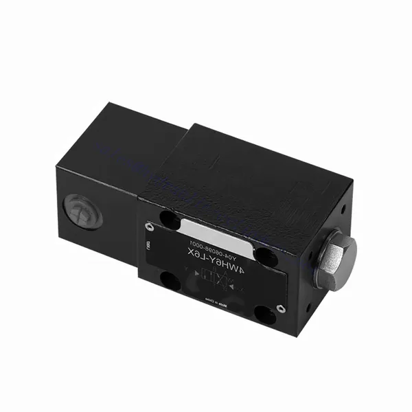
WH(D) 시리즈 유체 구동식 방향 유압 밸브
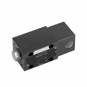

WH(D) 시리즈 유체 구동식 방향 유압 밸브는 유압 시스템에서 정밀한 제어와 효율적인 작동을 제공하도록 설계된 최첨단 제품입니다. 고급 기능과 안정적인 성능을 갖춘 이 밸브는 향상된 기능성과 다용성을 제공합니다.
WH(D) 시리즈 유체 구동식 방향 제어 유압 밸브는 유압 시스템에 향상된 제어 및 효율성을 제공합니다. 유체 구동 메커니즘, 정밀한 방향 제어 및 높은 유량 용량은 기능성과 다용성을 높여줍니다. 권장 사용 방법과 정기적인 유지보수를 준수하면 WH(D) 시리즈 밸브는 효율적이고 안정적인 작동을 지속적으로 제공합니다. WH(D) 시리즈 방향 제어 유압 밸브로 유압 시스템을 업그레이드하고 향상된 제어 및 효율성의 이점을 경험해 보세요.
WH(D) 시리즈 유체 구동식 방향 전환 유압 밸브의 주요 특징:
- 유체 구동 방식:
- WH(D) 시리즈 밸브는 유체 작동 방식을 사용하여 유압 시스템 내에서 정밀하고 반응성이 뛰어난 유체 흐름 제어를 가능하게 합니다.
- 이 작동 방식은 기존 메커니즘에 비해 정확성과 효율성이 향상되었습니다.
- 방향 제어:
- 이 유압 밸브는 유체 흐름의 방향을 정밀하게 제어할 수 있어 작업자가 원하는 흐름 경로를 쉽게 선택할 수 있도록 해줍니다.
- 유압 유체를 적절한 액추에이터 또는 구성 요소로 보내면 효율적이고 안정적인 작동이 보장됩니다.
- 고유량 용량:
- WH(D) 시리즈 밸브는 높은 유량을 처리하도록 설계되어 상당한 유체 흐름이 필요한 응용 분야에 적합합니다.
- 견고한 구조와 최적화된 내부 통로는 원활한 흐름과 최소한의 압력 강하를 보장합니다.
- 다재:
- 이 밸브는 활용도가 매우 높아 제조, 건설, 농업 등 다양한 산업 및 분야에서 사용할 수 있습니다.
- 이 시스템은 정밀한 제어와 효율적인 유체 관리가 필요한 유압 시스템에 통합될 수 있습니다.
WH(D) 시리즈 유체 작동식 방향 유압 밸브 파라미터:
NG6
| 설치 위치 | 선택 과목 | ||
| 유체 온도 범위 | ℃ | -30 ~ +80 (NBR 씰) | |
| -20 ~ +80(FKM 씰) | |||
| 포트 최대 작동 압력 | 포트 ABP | 술집 | 315 |
| 포트 T | 술집 | 60 | |
| 최대 유량 | 리터/분 | 60 | |
| 유동 단면 (스위치 중립 위치) | Q 타입 | mm2 | 기호 Q의 경우, 공칭 단면적은 6%입니다. |
| W형 | mm2 | 기호 W의 경우, 공칭 단면적은 3%입니다. | |
| 체액 | 미네랄 오일; 인산 에스테르 | ||
| 점도 범위 | mm2/에스 | 2.8에서 500까지 | |
| 오염 정도 | 최대 허용 유체 오염도: Class 9. NAS 1638 또는 20/18/15, ISO4406 | ||
| 무게 | 킬로그램 | 1.4 | |
NG10
| 설치 위치 | 선택 과목 | ||
| 유체 온도 범위 | ℃ | -30 ~ +80 (NBR 씰) | |
| -20 ~ +80(FKM 씰) | |||
| 포트 최대 작동 압력 | 포트 ABP | 술집 | 315 |
| 포트 T | 술집 | 60 | |
| 최대 유량 | 리터/분 | 120 | |
| 유동 단면 (스위치 중립 위치) | V형 | mm2 | 11(A/B → T);10.3(P → A/B) |
| W형 | mm2 | 2.5(A/B → T) | |
| Q 타입 | mm2 | 5.5(A/B → T) | |
| 체액 | 미네랄 오일; 인산 에스테르 | ||
| 점도 범위 | mm2/에스 | 2.8에서 500까지 | |
| 오염 정도 | 최대 허용 유체 오염도: Class 9. NAS 1638 또는 20/18/15, ISO4406 | ||
| 무게 | 킬로그램 | 4 | |
WH(D) 시리즈 유체 구동식 방향 전환 유압 밸브의 장점:
• 직접 작동식 방향 슬라이드 밸브
• 스크롤 휠은 90° 회전 가능합니다
• 19가지 표준 슬라이드 밸브 기능
WH(D) 시리즈 유체 구동식 방향 유압 밸브의 사용 방법:
- 시스템 통합:
- 원하는 유로 및 제어 요구 사항을 고려하여 유압 시스템 내에서 WH(D) 시리즈 밸브의 최적 위치를 파악합니다.
- Ensure compatibility with the system’s pressure and flow specifications.
- 적절한 브래킷이나 장착 액세서리를 사용하여 밸브를 단단히 고정하십시오.
- 유체 연결:
- 안전하고 누출 없는 연결을 위해 호환 가능한 유압 피팅과 호스를 선택하세요.
- Follow the manufacturer’s instructions for proper torque values during the installation process.
- 안정적인 밀봉을 위해 적절한 나사산 밀봉제나 테이프를 사용하세요.
- 작동:
- 밸브의 유체 작동 메커니즘을 숙지하고 사용 가능한 제어 방법을 이해하십시오.
- 작동 라인을 지정된 포트에 연결할 때, 올바른 식별과 연결 무결성을 확인하십시오.
- 제어 및 조정:
- WH(D) 시리즈 밸브를 작동시키려면 수동 레버, 솔레노이드 밸브 또는 기타 작동 장치와 같은 권장 제어 방법을 사용하십시오.
- 최적의 성능을 보장하기 위해 원하는 흐름 방향과 유량에 따라 밸브 설정을 조정하십시오.
유압 밸브는 어떻게 작동할까요?
A hydraulic valve is a critical component in a hydraulic system that controls the flow and direction of hydraulic fluid. It allows operators to regulate the movement and pressure of the liquid, enabling precise control over various hydraulic functions. Here’s a simplified explanation of how a hydraulic valve works:
- 밸브 구조:
- 유압 밸브는 일반적으로 밸브 본체로 구성되며, 밸브 본체에는 포트, 챔버 및 통로와 같은 다양한 내부 구성 요소가 들어 있습니다.
- 밸브 본체에는 유압 유체의 흐름을 제어하는 스풀이나 포펫과 같은 가동 부품도 포함되어 있습니다.
- 유체 흐름:
- 유압 밸브는 유압 시스템의 여러 부분에 연결되는 여러 개의 포트를 가지고 있습니다.
- 유압유는 유입구를 통해 밸브로 들어가 밸브 본체 내부의 통로를 따라 흐릅니다.
- 스풀 또는 포펫 움직임:
- 스풀 또는 포펫 메커니즘이 유압 밸브의 움직임을 제어합니다.
- 스풀은 표면에 홈이나 돌기가 가공된 원통형 부품이고, 포펫은 움직일 수 있는 플러그 모양의 요소입니다.
- 스풀이나 포펫이 특정 위치에 있으면 유압유가 특정 통로를 통해 흐르도록 하고 다른 통로는 차단합니다.
- 밸브 작동:
- 유압 밸브는 수동 레버, 솔레노이드 또는 파일럿 제어와 같은 다양한 방식으로 작동될 수 있습니다.
- 작동 메커니즘은 스풀 또는 포펫의 위치를 제어하여 어떤 통로가 열리거나 닫히는지를 결정합니다.
- 수동 밸브는 손으로 작동되는 반면, 솔레노이드 밸브는 전기 신호를 사용하여 스풀 또는 포펫을 움직입니다.
- 흐름 방향 및 제어:
- 유압 밸브는 스풀이나 포펫의 위치를 조정함으로써 유체 흐름 방향을 제어할 수 있습니다.
- For example, in a directional control valve, the spool’s position determines whether fluid flows from the inlet to the outlet or is redirected to other ports.
- 압력 제어 밸브나 유량 제어 밸브와 같은 다른 유압 밸브는 각각 유체의 압력이나 유량을 조절합니다.
- 압력 보상:
- 유압 밸브에는 시스템 내에서 일정한 압력을 유지하기 위해 압력 보상 메커니즘이 포함되는 경우가 많습니다.
- 이러한 메커니즘은 밸브가 압력 변화에 맞춰 조정되고 원하는 유량 또는 압력 수준을 유지하도록 합니다.
- 반환 또는 소진:
- 일부 유압 시스템에서 밸브는 유압 유체의 복귀 또는 배출 경로를 제공합니다.
- 이 밸브들은 특정 회로에서 더 이상 필요하지 않은 유체를 제어된 방식으로 방출하거나 저장소로 되돌려 보낼 수 있도록 합니다.
공장의 역량 및 용량:
(1) 조립
당사는 최고 수준의 독자적인 연구개발 조립 플랫폼을 보유하고 있습니다. 유압 실린더 생산 작업장은 4개의 반자동 리프팅 실린더 조립 라인과 1개의 자동 틸트 실린더 조립 라인을 갖추고 있으며, 연간 100만 개의 설계 생산 능력을 갖추고 있습니다. 특수 실린더 작업장은 다양한 사양의 반자동 세척 조립 시스템을 갖추고 있으며, 연간 20만 개의 설계 생산 능력을 갖추고 있습니다. 또한, 유명 CNC 가공 장비, 머시닝 센터, 고정밀 실린더 가공 특수 장비, 로봇 용접기, 자동 세척기, 자동 실린더 조립기, 자동 도장 생산 라인을 갖추고 있습니다. 300대 이상의 핵심 장비를 보유하고 있으며, 장비 자원의 최적 배치 및 효율적인 사용을 통해 제품의 정밀성 요구 사항을 충족하고 고품질 요구를 충족합니다.


(2) 가공
가공공장은 맞춤형 경사레일 터닝센터, 가공센터, 고속 호닝머신, 용접로봇 및 기타 관련 장비를 갖추고 있으며, 최대 내경 400mm, 최대 길이 6m의 원통형 튜브를 가공할 수 있습니다.


(3) 용접


(4) 도장 및 코팅
소형, 중형 실린더 자동 수성 페인트 코팅 라인을 통해 자동 로봇 로딩 및 언로딩과 자동 분무를 실현하며, 교대당 4000개의 설계 용량을 달성합니다.
또한, 우리는 60개의 케이스를 교대로 생산할 수 있는 설계 용량을 갖춘 파워 체인으로 구동되는 대형 실린더용 반자동 페인트 생산 라인을 보유하고 있습니다.


(5) 테스트
당사는 실린더의 성능이 요구 사항을 충족하는지 확인하기 위해 일류 검사 시설과 테스트 베드를 갖추고 있습니다.


저희는 최고의 유압 실린더 제조업체 중 하나입니다. 다양한 유압 실린더를 공급할 수 있으며, 관련 제품도 제공합니다. 농업용 기어박스저희는 전 세계 고객에게 제품을 수출해 왔으며, 탁월한 제품 품질과 애프터서비스를 통해 좋은 평판을 얻고 있습니다. 국내외 고객 여러분의 사업 상담, 정보 교환, 그리고 우리와 협력하다!