4WRE(E) Series Proportional Directional Hydraulic Valve
4WRE(E) Series Proportional Directional Hydraulic Valve
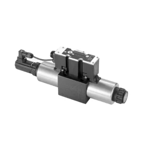
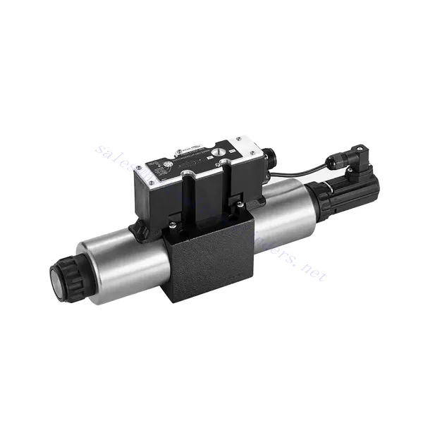
The 4WRE(E) series proportional directional hydraulic valve is a cutting-edge hydraulic component designed to deliver precise control and exceptional performance in hydraulic systems. This valve utilizes advanced proportional control technology to ensure accurate flow regulation and seamless directional changes.
The 4WRE(E) series proportional directional hydraulic valve empowers hydraulic systems with precise flow control, versatile directional changes, and energy efficiency. Its proportional control technology enables accurate and responsive flow adjustment, while the high flow capacity ensures reliable performance even in demanding applications. By following the recommended usage methods and maintenance guidelines, you can maximize the benefits and longevity of the 4WRE(E) series valve, elevating your hydraulic system to new levels of precision and performance. Upgrade your hydraulic setup today and experience the power of the 4WRE(E) series proportional directional hydraulic valve.
4WRE(E) Series Proportional Directional Hydraulic Valve Key Characteristics:
- Proportional Control Technology:
- The 4WRE(E) series valve features advanced proportional control technology, allowing for precise and proportional flow adjustment according to control signals.
- This feature enables accurate and responsive control, resulting in improved system performance and efficiency.
- Versatile Directional Control:
- With its proportional directional control capability, this valve offers versatile control over hydraulic fluid direction.
- It allows for seamless activation and deactivation of hydraulic components such as cylinders, motors, and actuators in different directions, enhancing system flexibility and productivity.
- Didelis srautas:
- The 4WRE(E) series valve is designed to handle high flow rates, making it suitable for applications requiring substantial hydraulic power.
- Tvirta konstrukcija užtikrina patikimą veikimą net ir sudėtingomis sąlygomis, užtikrindama nuoseklų ir efektyvų srauto valdymą.
- Energijos vartojimo efektyvumas:
- By employing advanced flow control mechanisms, this valve minimizes pressure drops and optimizes energy usage.
- Tai padeda sumažinti energijos suvartojimą, todėl sutaupoma lėšų ir gaunama nauda aplinkai.
4WRE(E) Series Proportional Directional Hydraulic Valve Parameter:
| Hidraulinis | ||||
| Montavimo padėtis | optional, preferably horizontal | |||
| Dydis | 6 | 10 | ||
| Svoris | 4WRE…L2X | Kg | 2.2 | 6.3 |
| 4WREE…L2X | 2.4 | 6.5 | ||
| Nominal flow qnom at Δp = 10 bar | L/min | 8 16 32 | 25 50 75 | |
| Histerezė | % | ≤0.1 | ||
| Reversal span | % | ≤0.05 | ||
| Pakartojamumas | % | ≤0.05 | ||
| Maks. darbinis slėgis | Port s A B P | baras | 315 | |
| T prievadas | baras | 210 | ||
| Skystis | Mineralinė alyva, tinkama NBR ir FKM sandarikliams | |||
| Fosfato esteris FKM sandarinimui | ||||
| Ambient air temperature range | 4WRA…L2X | ℃ | -20℃ to 70℃ (-4°F to 158°F) | |
| 4WRAE…L2X | ℃ | -20℃ to 50℃ (-4°F to 122°F) | ||
| Klampumo diapazonas | mm²/s | 20 to 380 (preferably 30 to 46) | ||
| Užterštumo laipsnis | NAS1638 class9 or ISO 4406 class 20/18/15 | |||
| Elektros duomenys | ||||
| 1)solenoid | ||||
| Dydis | 6 | 10 | ||
| Įtampos tipas | DC | |||
| Komandos vertės signalas | ±10V or 4~20mA | |||
| Max.current per solenoid | A | 2.5 | ||
| Ritės varža | Cold value | Ω | 2.7 | 3.7 |
| Maksimali šiluminė vertė | 4.05 | 5.55 | ||
| Duty | % | ED 100% | ||
| Ritės temperatūra | ℃ | 150 | ||
| Vožtuvų apsauga pagal EN 60529 | IP65 | |||
| 2) Control electronics | ||||
| Ampilfier | 4WRE…L2X | VT-VSPA2-L2X | ||
| 4WREE…L2X | integrated(OBE) | |||
| Operating voltage | Nominal voltage | VDC | 24 | |
| Lower limiting value | V. | 19.4 | ||
| Upper limiting value | V. | 35 | ||
| Amplifier current consumption | Imax | A | < 2 | |
| Imax | A | 3 | ||
4WRE(E) Series Proportional Directional Hydraulic Valve Advantages:
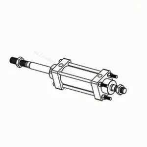
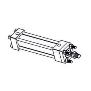
• Direct-acting proportional directional valve, used to control the flow and direction of liquid flow
• Panel type installation
• The proportional solenoid actuates the valve core through the threaded connection, and the coil can be removed separately
• Spool position feedback
• Optional with built-in amplifier, 4WRAE…L2X type input can be A1 or F1
• Supporting supply of external amplifier
Usage Method Of 4WRE(E) Series Proportional Directional Hydraulic Valve:
- Sistemos vertinimas:
- Įvertinkite savo hidraulinę sistemą ir nustatykite konkrečius srauto ir krypties valdymo reikalavimus.
- Determine if the 4WRE(E) series valve is suitable based on its flow capacity, pressure rating, and compatibility with your system.
- Vožtuvo pasirinkimas:
- Select the appropriate variant of the 4WRE(E) series valve based on your system parameters, flow requirements, and directional control needs.
- Atsižvelkite į tokius veiksnius kaip maksimalus srautas, slėgio lygis, atsako laikas ir eksploatavimo sąlygos.
- Įrengimas:
- Atidžiai laikykitės gamintojo montavimo instrukcijų, užtikrindami tinkamą vožtuvo sulygiavimą ir saugų pritvirtinimą.
- Make leak-free connections and ensure correct flow direction alignment to guarantee optimal performance.
- Control Signal Connection:
- Prijunkite vožtuvo valdymo signalo laidus prie tinkamo valdymo įtaiso, pvz., proporcinio stiprintuvo arba elektroninio valdymo bloko.
- Užtikrinkite tinkamą laidų sujungimą ir suderinamumą tarp vožtuvo ir valdymo įtaiso, kad valdymas būtų tikslus ir greitas.
How To Adjust Valves With Hydraulic Lifters?
Adjusting valve lash on hydraulic lifters is a crucial maintenance task to ensure proper engine performance and prevent issues such as noisy valves or reduced power. Here’s a step-by-step guide on how to adjust valve lash on hydraulic lifters:
- Paruošimas:
- Ensure the engine is off and cool before starting the adjustment process.
- Familiarize yourself with the engine’s firing order and the specific valve lash specifications provided by the manufacturer for your engine model.
- Identify the Correct Cylinder:
- Locate the firing position of the engine by referring to the engine’s firing order diagram.
- Identify the cylinder that corresponds to the specific valve you want to adjust.
- Cilindro padėtis:
- Rotate the engine crankshaft manually using a socket wrench or the engine’s built-in turning mechanism.
- Position the cylinder you want to adjust at the top dead center (TDC) on the compression stroke. You can do this by aligning the timing marks on the crankshaft pulley or using a piston stop tool.
- Loosen the Rocker Arm:
- Locate the rocker arm on the specific valve you want to adjust.
- Loosen the rocker arm nut or adjuster screw using an appropriate wrench or socket.
- Adjust the Valve Lash:
- With the rocker arm loose, you can now adjust the valve lash. The valve lash is the clearance between the rocker arm and the valve stem.
- Use a feeler gauge to measure the existing valve lash. Insert the appropriate thickness gauge between the rocker arm and the valve stem.
- If the clearance is too tight, meaning the feeler gauge does not fit or has excessive resistance, you need to increase the valve lash. If the clearance is too loose, meaning the feeler gauge slides in too easily, you need to decrease the valve lash.
- To adjust the valve lash, tighten or loosen the rocker arm nut or adjuster screw accordingly. Refer to the manufacturer’s specifications for the recommended amount of adjustment to be made.
- Recheck the Valve Lash:
- After making the adjustment, recheck the valve lash using the feeler gauge to ensure it falls within the recommended specifications.
- Repeat the adjustment process if necessary until the correct valve lash is achieved.
- Repeat for Other Cylinders:
- Proceed to the next cylinder in the firing order and repeat steps 4 to 6 for each cylinder you want to adjust.
- Remember to rotate the crankshaft and position each cylinder at TDC on the compression stroke before adjusting its valve lash.
- Secure the Rocker Arm:
- Once the valve lash is properly adjusted for each cylinder, tighten the rocker arm nut or adjuster screw to the manufacturer’s recommended torque specification.
- Double-check that the valve lash remains within the specified range after tightening.
- Galutiniai patikrinimai:
- Rotate the engine crankshaft a few times to ensure smooth rotation and check for any unusual noises or resistance.
- Start the engine and listen for any abnormal valve noises. If you hear excessive tapping or knocking, recheck the valve lash adjustment.
Gamyklos pajėgumai ir talpa:
(1) Surinkimas
Turime pirmos klasės nepriklausomą tyrimų ir plėtros surinkimo platformą. Hidraulinių cilindrų gamybos ceche yra keturios pusiau automatinės kėlimo cilindrų surinkimo linijos ir viena automatinė pakreipimo cilindrų surinkimo linija, kurių projektinis metinis gamybos pajėgumas yra 1 milijonas vienetų. Specialiųjų cilindrų ceche įrengta įvairių specifikacijų pusiau automatinė valymo surinkimo sistema, kurios projektinis metinis gamybos pajėgumas yra 200 000 vienetų, ir garsi CNC apdirbimo įranga, apdirbimo centras, didelio tikslumo cilindrų apdirbimo speciali įranga, robotinis suvirinimo aparatas, automatinis valymo aparatas, automatinis cilindrų surinkimo aparatas ir automatinė dažymo gamybos linija. Esama daugiau nei 300 rinkinių (komplektų) kritinė įranga. Optimalus įrangos išteklių paskirstymas ir efektyvus naudojimas užtikrina gaminių tikslumo reikalavimus ir aukštus gaminių kokybės poreikius.


(2) Apdirbimas
Mechaninio apdirbimo ceche įrengtas pritaikytas nuožulnaus bėgio tekinimo centras, apdirbimo centras, greitaeigis galandimo staklės, suvirinimo robotas ir kita susijusi įranga, galinti apdirbti cilindrinius vamzdžius, kurių maksimalus vidinis skersmuo yra 400 mm, o maksimalus ilgis – 6 metrai.

(3) Suvirinimas

(4) Dažymas ir dengimas
Su mažomis ir vidutinio dydžio cilindrinėmis automatinėmis vandens pagrindo dažų dengimo linijomis, siekiant automatinio robotų pakrovimo ir iškrovimo bei automatinio purškimo, projektinis pajėgumas yra 4000 vienetų per pamainą;
Taip pat turime pusiau automatinę didelių cilindrų dažų gamybos liniją, varomą grandinės, kurios projektinis našumas yra 60 dėžių per pamainą.


(5) Testavimas
Turime aukščiausios klasės patikros patalpas ir bandymų stendus, kad užtikrintume, jog baliono veikimas atitinka reikalavimus.

Esame vienas geriausių hidraulinių cilindrų gamintojų. Galime pasiūlyti išsamius hidraulinius cilindrus. Taip pat teikiame atitinkamus žemės ūkio pavarų dėžėsMes eksportuojame savo gaminius klientams visame pasaulyje ir pelnėme gerą reputaciją dėl aukščiausios gaminių kokybės ir aptarnavimo po pardavimo. Mes laukiame klientų šalyje ir užsienyje, norinčių susisiekti su mumis derėtis dėl verslo, keistis informacija ir... bendradarbiauti su mumis!