

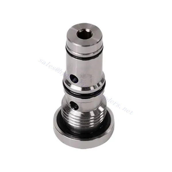
KSF Series Shuttle Hydraulic Valve

The KSF series shuttle hydraulic valve is a high-performance component designed to enhance fluid flow control in hydraulic systems. With its advanced design and robust construction, this valve offers precise and reliable operation, ensuring optimal system performance.
The KSF series shuttle hydraulic valve is an exceptional solution for fluid flow control in hydraulic systems. With its shuttle valve functionality, robust construction, high flow capacity, and compact design, this valve optimizes performance and ensures efficient utilization of hydraulic power. By following the recommended usage methods and maintenance practices, the KSF series shuttle hydraulic valve delivers reliable operation and extends the lifespan of hydraulic systems. Upgrade your hydraulic system with the KSF series shuttle hydraulic valve and experience enhanced fluid flow control for improved overall system performance.
KSF Series Shuttle Hydraulic Valve Key Characteristics:
- Shuttle Valve Functionality:
- The KSF series valve incorporates a shuttle valve design to divert hydraulic fluid flow between two circuits.
- It enables the selection of the circuit with higher pressure, ensuring efficient utilization of hydraulic power and preventing pressure imbalances.
- Tvirta konstrukcija:
- Built with durable materials, the KSF series shuttle hydraulic valve is designed to withstand high-pressure environments and demanding operating conditions.
- Its robust construction ensures longevity and reliability, minimizing downtime and maintenance costs.
- Didelis srautas:
- The KSF series valve offers a high flow capacity, allowing for efficient transfer of hydraulic fluid between circuits.
- It minimizes pressure drops, ensuring maximum power delivery and system performance.
- Compact and Versatile Design:
- The valve’s compact design makes it suitable for installations with limited space or weight constraints.
- Its versatility allows easy integration into various hydraulic systems, including industrial machinery, mobile equipment, and power units.
KSF Series Shuttle Hydraulic Valve Parameter:
| Dydis | NG6 | NG10 | |
| Skysčio temperatūros diapazonas | ℃ | -30 to +80 (NBR seals) | |
| -20 iki +80 (FKM sandarikliai) | |||
| Klampumo diapazonas | mm2/s | Recommandation 30~80, permission 20~380 | |
| Maks. darbinis slėgis | baras | 350 | |
| Maks. srautas | L/min | 40 | 60 |
| Svoris | kg | 0.5 | 0.8 |
| Skystis | Mineralinė alyva, tinkama NBR ir FKM sandarikliams | ||
| Fosfato esteris FKM sandarinimui | |||
| Užterštumo laipsnis | Didžiausias leistinas skysčių užterštumo laipsnis: 9 klasė. NAS 1638 arba 20/18/15, ISO4406 | ||
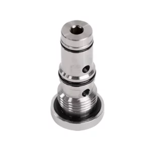
KSF Series Shuttle Hydraulic Valve Advantages:
• Seal without leakage
• Cartridge structure for oil block installation
Usage Method Of KSF Series Shuttle Hydraulic Valve:
- Sistemos analizė:
- Before installation, perform a comprehensive hydraulic system analysis to determine specific requirements and operating parameters.
- Consider factors such as flow rates, pressure ratings, and compatibility with the KSF series shuttle hydraulic valve.
- Vožtuvo pasirinkimas:
- Choose the appropriate KSF series valve variant based on the system’s requirements and specifications.
- Consider factors like flow capacity, pressure ratings, and compatibility with other system components.
- Įrengimas:
- Follow the manufacturer’s instructions for properly installing the KSF series shuttle hydraulic Valve in the hydraulic system.
- Ensure a secure fit, proper alignment with the fluid flow path, and adequate sealing to prevent leaks.
- Circuit Connection:
- Connect the inlet and outlet ports of the valve to the corresponding circuits that require fluid diversion.
- Ensure proper identification and connection of the high-pressure circuit and low-pressure circuit.
How Does A Hydraulic Flow Control Valve Work?
A hydraulic flow control valve is a device used to regulate and control the speed of hydraulic fluid within a hydraulic system. It allows the operator to adjust the flow rate of the liquid, thereby preventing the speed of hydraulic actuators or controlling the rate of energy transfer. Here’s an explanation of how a hydraulic flow control valve works:
- Vožtuvo konstrukcija:
- A hydraulic flow control valve typically consists of a valve body with inlet and outlet ports, a movable spool or poppet, and an actuating mechanism.
- The valve body contains internal passages and chambers that control the flow of hydraulic fluid.
- Fluid Flow Paths:
- The flow control valve has an inlet port that connects to the hydraulic power source, such as a pump, and an outlet port that connects to the hydraulic actuator or another component.
- The valve provides different flow paths for fluid, allowing it to be controlled and regulated.
- Spool or Poppet:
- The valve body houses a movable spool or poppet that regulates the flow of hydraulic fluid.
- The spool can slide within the valve body, while the poppet can move linearly or rotate to open or close specific passages.
- Actuating Mechanism:
- Hydraulic flow control valves can be actuated manually, electrically, or through other means, depending on the specific design and application requirements.
- Manual actuation involves adjusting a handle, knob, or lever to position the spool or poppet.
- Electrical actuation utilizes solenoids that receive electrical signals to shift the spool or poppet, allowing for remote control and automation.
- Valve Positions:
- A hydraulic flow control valve typically has multiple positions that the spool or poppet can assume, each corresponding to a specific flow rate.
- The valve may have a range of preset positions or offer continuous adjustment for fine-tuning the flow rate.
- As the spool or poppet shifts, it aligns with specific passages, opening or closing them to control the fluid flow.
- Flow Regulation:
- By adjusting the position of the spool or poppet, the operator can control the size of the flow passages, thereby regulating the flow rate of the hydraulic fluid.
- When the passages are fully open, the fluid flows freely, allowing for maximum flow rate.
- Partially closing the passages restricts the flow, reducing the flow rate and controlling the speed of hydraulic actuators.
- Pressure Compensation:
- Some hydraulic flow control valves incorporate pressure compensation mechanisms to maintain a consistent flow rate despite changes in system pressure.
- These mechanisms ensure that the desired flow rate is maintained even when the system encounters variations in load or pressure.
Gamyklos pajėgumai ir talpa:
(1) Surinkimas
Turime pirmos klasės nepriklausomą tyrimų ir plėtros surinkimo platformą. Hidraulinių cilindrų gamybos ceche yra keturios pusiau automatinės kėlimo cilindrų surinkimo linijos ir viena automatinė pakreipimo cilindrų surinkimo linija, kurių projektinis metinis gamybos pajėgumas yra 1 milijonas vienetų. Specialiųjų cilindrų ceche įrengta įvairių specifikacijų pusiau automatinė valymo surinkimo sistema, kurios projektinis metinis gamybos pajėgumas yra 200 000 vienetų, ir garsi CNC apdirbimo įranga, apdirbimo centras, didelio tikslumo cilindrų apdirbimo speciali įranga, robotinis suvirinimo aparatas, automatinis valymo aparatas, automatinis cilindrų surinkimo aparatas ir automatinė dažymo gamybos linija. Esama daugiau nei 300 rinkinių (komplektų) kritinė įranga. Optimalus įrangos išteklių paskirstymas ir efektyvus naudojimas užtikrina gaminių tikslumo reikalavimus ir aukštus gaminių kokybės poreikius.


(2) Apdirbimas
Mechaninio apdirbimo ceche įrengtas pritaikytas nuožulnaus bėgio tekinimo centras, apdirbimo centras, greitaeigis galandimo staklės, suvirinimo robotas ir kita susijusi įranga, galinti apdirbti cilindrinius vamzdžius, kurių maksimalus vidinis skersmuo yra 400 mm, o maksimalus ilgis – 6 metrai.


(3) Suvirinimas


(4) Dažymas ir dengimas
Su mažomis ir vidutinio dydžio cilindrinėmis automatinėmis vandens pagrindo dažų dengimo linijomis, siekiant automatinio robotų pakrovimo ir iškrovimo bei automatinio purškimo, projektinis pajėgumas yra 4000 vienetų per pamainą;
Taip pat turime pusiau automatinę didelių cilindrų dažų gamybos liniją, varomą grandinės, kurios projektinis našumas yra 60 dėžių per pamainą.


(5) Testavimas
Turime aukščiausios klasės patikros patalpas ir bandymų stendus, kad užtikrintume, jog baliono veikimas atitinka reikalavimus.


Esame vienas geriausių hidraulinių cilindrų gamintojų. Galime pasiūlyti išsamius hidraulinius cilindrus. Taip pat teikiame atitinkamus žemės ūkio pavarų dėžėsMes eksportuojame savo gaminius klientams visame pasaulyje ir pelnėme gerą reputaciją dėl aukščiausios gaminių kokybės ir aptarnavimo po pardavimo. Mes laukiame klientų šalyje ir užsienyje, norinčių susisiekti su mumis derėtis dėl verslo, keistis informacija ir... bendradarbiauti su mumis!