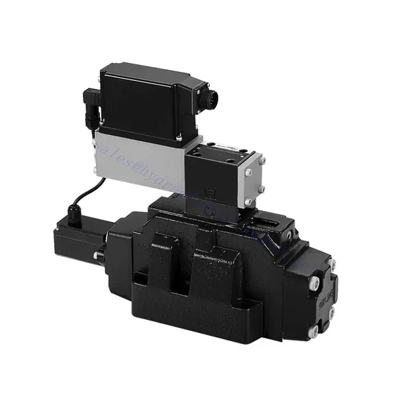
4WRLE Series Pilot Operated Proportional Directional Hydraulic Valve
Kaip vienas iš hidraulinių cilindrų gamintojų, tiekėjų ir mechaninių produktų eksportuotojų, mes siūlome hidraulinius cilindrus ir daugelį kitų produktų.
Susisiekite su mumis dėl išsamesnės informacijos.
Paštas:sales@hydraulic-cylinders.net
Hidraulinių cilindrų gamintojas, tiekėjas ir eksportuotojas.
4WRLE Series Pilot Operated Proportional Directional Hydraulic Valve
The 4WRLE series pilot-operated proportional directional hydraulic valve is a cutting-edge hydraulic component that revolutionizes fluid control in hydraulic systems. This valve combines pilot-operated technology with proportional directional control, offering precise flow regulation and exceptional efficiency.
The 4WRLE series pilot-operated proportional directional hydraulic valve elevates hydraulic control to new heights of precision and efficiency. With its pilot-operated technology and proportional directional control, this valve ensures accurate flow regulation, optimized energy consumption, and enhanced system performance. By following the recommended usage methods and maintenance guidelines, you can unleash the full potential of the 4WRLE series valve and achieve superior hydraulic control. Upgrade your hydraulic system today and experience the power of precision with the 4WRLE series pilot-operated proportional directional hydraulic valve.
4WRLE Series Pilot Operated Proportional Directional Hydraulic Valve Key Characteristics:
- Pilot Operated Technology:
- The 4WRLE series valve incorporates pilot-operated technology, allowing precise fluid flow control and pressure regulation.
- This technology enables efficient energy usage and reduces heat generation, resulting in improved overall system performance and reduced operating costs.
- Proportional Directional Control:
- With its proportional directional control capability, this valve provides accurate and balanced flow adjustment based on control signals.
- The proportional control allows for smooth and precise control of hydraulic actuators, enhancing system performance and minimizing wear and tear.
- Universalus funkcionalumas:
- The 4WRLE series valve offers versatile control over fluid direction, making it suitable for a wide range of hydraulic applications.
- Whether it’s controlling cylinders, motors, or other hydraulic components, this valve ensures seamless activation and deactivation in different directions, enhancing system flexibility and adaptability.
- Didelis srautas:
- Designed to handle high flow rates, the 4WRLE series valve delivers exceptional performance even in demanding applications.
- Its robust construction and optimized flow channels ensure reliable operation and consistent flow control, meeting the requirements of high-power hydraulic systems.
4WRLE Series Pilot Operated Proportional Directional Hydraulic Valve Parameter:
NG6
| Bendra | |||||||
| Dizainas | Spool valve, direct operated, with steel sleeve | ||||||
| Įjungimas | Proportional solenoid with position control, OBE | ||||||
| Ryšio tipas | Subplate mounting, porting pattern according to ISO 4401-03-02-0-05 | ||||||
| Montavimo padėtis | Any | ||||||
| Aplinkos temperatūros diapazonas | ℃ | -20…+50 | |||||
| Svoris | Kg | about 2.75 | |||||
| Maximum vibration resistance (test condition) | Max. 25 g, space vibration test in all directions (24h) | ||||||
| Hidraulinis (measured at p=100bar, with HLP46 at ϑoil = 40℃ ±5℃) | |||||||
| Slėginis skystis | Mineral oil (HL, HLP)to DIN 51 524 | ||||||
| Klampumo diapazonas | rekomenduojama | mm²/s | 20…100 | ||||
| maks. leidžiamas | mm²/s | 10…800 | |||||
| Slėginio skysčio temperatūros diapazonas | ℃ | nuo -20 iki +70 | |||||
| Didžiausias leidžiamas slėginio skysčio užterštumo laipsnis Grynumo klasė pagal ISO 4406 (c) | 18/16/13 klasė | ||||||
| Rated flow (Δp = 35 bar per edge) | L/min | 2 | 4 | 12 | 24 | 40 | |
| Maks. darbinis slėgis | baras | Port A、B、P:315 | |||||
| Maks. slėgis | baras | T prievadas: 250 | |||||
| Leakage flow at 100 bar | Linear | cm³/min | <150 | <180 | <300 | <500 | <900; |
| Nonlinear | cm³/min | / | / | / | <300 | <450; | |
| Statinis/Dinaminis | |||||||
| Histerezė | % | ≤0.2 | |||||
| Actuating time for signal step 0 … 100% | ms | 10 | |||||
| Temperature drift | Zero shift < 1% at ΔT=40℃ | ||||||
| Zero compensation | Ex factory ±1% | ||||||
| Electric, control electronics integrated in the valve | |||||||
| Relative duty cycle | % | 100ED | |||||
| Apsaugos laipsnis | IP65 | ||||||
| Connection | Plug-in connector 6P+PE, DIN 43563 | ||||||
| Supply voltage Terminal A Terminal B |
24VDCnom | ||||||
| min. 21VDC / max. 40VDC | |||||||
| 0V (ripple max. 2) | |||||||
| Fuse protection, external | AF | 2.5 | |||||
| nput, version “A1” Terminal D (UE) Terminal E |
Differential amplifier, Ri = 100 kΩ | ||||||
| 0…±10V | |||||||
| 0V | |||||||
| Input, version “F1” Terminal D (ID-E) Terminal E (ID-E) |
Load, Rsh = 200 Ω | ||||||
| 4…12…20mA | |||||||
| Current loop ID-E return | |||||||
| Test signal, version “A1” Terminal F (UTest) Terminal C |
LVDT | ||||||
| 0…±10V | |||||||
| Reference 0 V | |||||||
| Test signal, version “F1” Terminal F ( I F-C ) Terminal C ( I F-C ) |
LVDT signal 4 … (12) … 20 mA on external load 200 … 500 Ωmaximum | ||||||
| 4 … (12) … 20mA (output) | |||||||
| Current loop IF-C return | |||||||
| Adjustment | Calibrated before delivery, see characteristic curves | ||||||
NG10
| Bendra | |||||
| Dizainas | Spool valve, directly operated, with steel sleeve | ||||
| Įjungimas | Proportional solenoid with position control, OBE | ||||
| Ryšio tipas | Plate port, porting pattern (ISO 4401-05-04-0-05) | ||||
| Montavimo padėtis | Any | ||||
| Aplinkybės, temperatūros diapazonas | ℃ | -20…+50 | |||
| Svoris | Kg | about 7.1 | |||
| Maximum vibration resistance (test condition) | Max. 25 g, space vibration test in all directions (24h) | ||||
| Hydraulic (measured with HLP 46, ϑoil =40℃ ±5℃) | |||||
| Slėginis skystis | Hydraulic oil according to DIN 51524…535 | ||||
| Klampumo diapazonas | rekomenduojama | mm²/s | 20…100 | ||
| Max. permitted | mm²/s | 10…800 | |||
| Slėginio skysčio temperatūros diapazonas | ℃ | nuo -20 iki +70 | |||
| Max. admissible degree of contamination of the hydraulic fluid,cleanliness class according to ISO 4406 (c) | 18/16/13 klasė | ||||
| Rated flow(Δp = 35 bar per edge) | L/min | 50 | 100 | ||
| Maks. darbinis slėgis | baras | Port P A B: 315 | |||
| Maks. slėgis | baras | T prievadas: 250 | |||
| Leakage flow at 100 bar | Linear | cm³/min | <1200 | <1500 | |
| Nonlinear | cm³/min | <600 | <600 | ||
| Statinis/Dinaminis | |||||
| Histerezė | % | ≤0.2 | |||
| Actuating time for signal step 0 … 100% | ms | 25 | |||
| Temperature drift | Zero shift < 1% at ΔT=40℃ | ||||
| Zero compensation | Ex factory ±1% | ||||
| Electric, control electronics integrated in the valve | |||||
| Relative duty cycle | % | 100ED | |||
| Apsaugos laipsnis | IP65(with mating connector mounted and locked ) | ||||
| Connection | Mating connector 6P+PE, DIN 43563 | ||||
| Supply voltage Terminal A Terminal B |
24VDCnom | ||||
| min. 21VDC / max. 40VDC | |||||
| Ripple max. 2 VDC | |||||
| Fuse protection, external | AF | 2.5 | |||
| Input, version “A1” Terminal D (UE) Terminal E |
Differential amplifier, Ri = 100 kΩ | ||||
| 0…±10V | |||||
| 0V | |||||
| Input, version “F1” Terminal D (ID-E) Terminal E (ID-E) |
Load, Rsh = 200 | ||||
| 4…12…20mA | |||||
| Current loop ID-E return | |||||
| Test signal, version “A1” Terminal F (UTest) Terminal C |
LVDT | ||||
| 0…±10V | |||||
| Reference 0 V | |||||
| Test signal, version “F1” Terminal F ( I F-C ) Terminal C ( I F-C ) |
LVDT | ||||
| 4…20 mA output | |||||
| Current loop IF-C feedback | |||||
4WRLE Series Pilot Operated Proportional Directional Hydraulic Valve Advantages:
• Direct-acting servo solenoid valve with control piston and valve sleeve, with servo performance
• Single-side drive, optional, with power-off safety function
Control solenoid with built-in feedback and integrated amplifier board (OBE), factory preset
• Electrical connection 6P+PE signal input differential amplifier with interface, input optional A1: ±10V, or interface F1: 4…20mA (Rsh =200Ω)
• Panel mounting: the mounting surface complies with ISO 4401-03-02
Usage Method Of 4WRLE Series Pilot Operated Proportional Directional Hydraulic Valve:
- Sistemos vertinimas:
- Evaluate your hydraulic system and define the specific flow and directional control requirements.
- Identify whether the 4WRLE series valve is compatible with your system based on factors such as flow capacity, pressure rating, and compatibility with your application.
- Vožtuvo pasirinkimas:
- Select the appropriate variant of the 4WRLE series valve based on your system parameters, flow requirements, and directional control needs.
- Consider factors such as maximum flow rate, pressure rating, response time, and environmental operating conditions.
- Įrengimas:
- Follow the manufacturer’s installation instructions carefully to ensure proper alignment and secure valve mounting.
- Create leak-free connections and ensure correct flow direction alignment to guarantee optimal performance.
- Valdymo signalo integravimas:
- Prijunkite vožtuvo valdymo signalo laidus prie tinkamo valdymo įtaiso, pvz., proporcinio stiprintuvo arba elektroninio valdymo bloko.
- Ensure proper wiring and compatibility between the valve and control device to achieve accurate and responsive control.
How To Hook Up A Hydraulic Flow Control Valve?
To hook up a hydraulic flow control valve, follow these steps:
- Nustatykite vožtuvo tipą: Determine the specific type of flow control valve you are working with. Common types include needle valves, adjustable flow control valves, or pressure-compensated flow control valves. Ensure that the valve is suitable for your application and compatible with your hydraulic system.
- Surinkite reikiamus įrankius ir medžiagas: Collect the necessary tools and materials, including appropriate hydraulic fittings, adapters, hoses, and wrenches.
- Paruoškite hidraulinę sistemą: Shut down the hydraulic system and relieve any pressure in the system by activating the relief valve or retracting any hydraulic cylinders. This step is crucial for safety.
- Nustatykite srauto kryptį: Identify the flow direction in your hydraulic system. Typically, the flow direction is indicated by arrows on the hydraulic components. Ensure that you understand the correct flow direction before proceeding.
- Raskite įrengimo tašką: Determine the optimal location to install the flow control valve in your hydraulic system. Consider factors such as accessibility, proximity to the actuator or hydraulic component, and ease of adjustment.
- Vožtuvo montavimas: Securely mount the flow control valve in the chosen location using appropriate brackets or clamps. Ensure the valve is positioned correctly, aligning the inlet and outlet ports with the flow direction.
- Prijunkite įleidimo ir išleidimo angas: Attach hydraulic hoses or tubing to the inlet and outlet ports of the flow control valve. Use suitable hydraulic fittings and adapters to create a leak-free connection. Tighten the connections using wrenches to ensure a secure fit, but avoid over-tightening.
- Adjust the Flow Control: Depending on the type of flow control valve, it may have adjustable features such as a needle valve or a flow control knob. Adjust the valve according to your desired flow rate or speed. Refer to the manufacturer’s instructions for specific adjustment procedures.
- Sistemos testavimas: Once the flow control valve is installed and adjusted, slowly restore hydraulic system pressure. Test the system to ensure that the flow control valve is functioning correctly. Monitor the flow rate or speed of the hydraulic actuator to verify that it is within the desired range.
- Fine-tune and Monitor: Adjust the flow control valve to achieve the desired flow rate or speed. Regularly monitor the hydraulic system for leaks, pressure inconsistencies, or unusual behavior.
Gamyklos pajėgumai ir talpa:
(1) Surinkimas
Turime pirmos klasės nepriklausomą tyrimų ir plėtros surinkimo platformą. Hidraulinių cilindrų gamybos ceche yra keturios pusiau automatinės kėlimo cilindrų surinkimo linijos ir viena automatinė pakreipimo cilindrų surinkimo linija, kurių projektinis metinis gamybos pajėgumas yra 1 milijonas vienetų. Specialiųjų cilindrų ceche įrengta įvairių specifikacijų pusiau automatinė valymo surinkimo sistema, kurios projektinis metinis gamybos pajėgumas yra 200 000 vienetų, ir garsi CNC apdirbimo įranga, apdirbimo centras, didelio tikslumo cilindrų apdirbimo speciali įranga, robotinis suvirinimo aparatas, automatinis valymo aparatas, automatinis cilindrų surinkimo aparatas ir automatinė dažymo gamybos linija. Esama daugiau nei 300 rinkinių (komplektų) kritinė įranga. Optimalus įrangos išteklių paskirstymas ir efektyvus naudojimas užtikrina gaminių tikslumo reikalavimus ir aukštus gaminių kokybės poreikius.


(2) Apdirbimas
Mechaninio apdirbimo ceche įrengtas pritaikytas nuožulnaus bėgio tekinimo centras, apdirbimo centras, greitaeigis galandimo staklės, suvirinimo robotas ir kita susijusi įranga, galinti apdirbti cilindrinius vamzdžius, kurių maksimalus vidinis skersmuo yra 400 mm, o maksimalus ilgis – 6 metrai.

(3) Suvirinimas

(4) Dažymas ir dengimas
Su mažomis ir vidutinio dydžio cilindrinėmis automatinėmis vandens pagrindo dažų dengimo linijomis, siekiant automatinio robotų pakrovimo ir iškrovimo bei automatinio purškimo, projektinis pajėgumas yra 4000 vienetų per pamainą;
Taip pat turime pusiau automatinę didelių cilindrų dažų gamybos liniją, varomą grandinės, kurios projektinis našumas yra 60 dėžių per pamainą.


(5) Testavimas
Turime aukščiausios klasės patikros patalpas ir bandymų stendus, kad užtikrintume, jog baliono veikimas atitinka reikalavimus.

Esame vienas geriausių hidraulinių cilindrų gamintojų. Galime pasiūlyti išsamius hidraulinius cilindrus. Taip pat teikiame atitinkamus žemės ūkio pavarų dėžėsMes eksportuojame savo gaminius klientams visame pasaulyje ir pelnėme gerą reputaciją dėl aukščiausios gaminių kokybės ir aptarnavimo po pardavimo. Mes laukiame klientų šalyje ir užsienyje, norinčių susisiekti su mumis derėtis dėl verslo, keistis informacija ir... bendradarbiauti su mumis!
Hidraulinio cilindro pritaikymas:
