


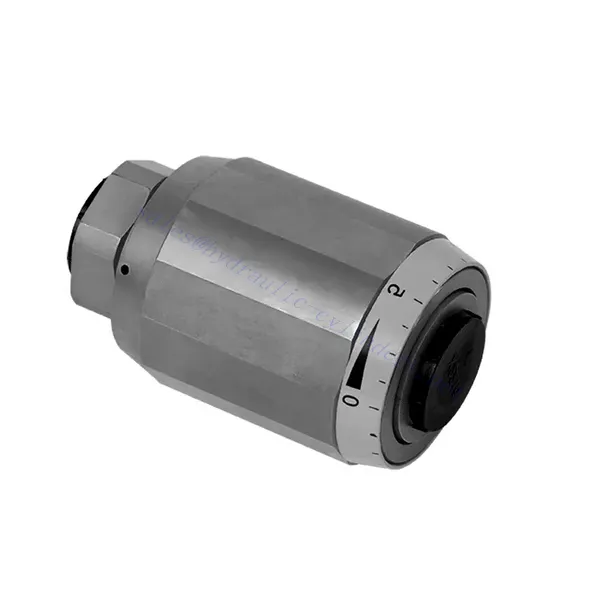
MG/MK Series Throttle And Throttle Check Hydraulic Valve
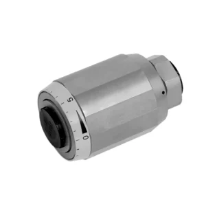

The MG/MK series throttle and throttle check hydraulic valve is a versatile and high-performance hydraulic component designed to optimize control and efficiency in hydraulic systems. With its unique throttle and throttle check functionality, this valve offers precise flow control and ensures the smooth operation of hydraulic actuators.
The MG/MK series throttle and throttle check hydraulic valve is a versatile and reliable solution for precise flow control and enhanced system efficiency. With its throttle functionality, throttle check feature, and customizable flow control options, this valve delivers exceptional performance in various hydraulic applications. Following the recommended usage methods and maintenance guidelines, operators can ensure the longevity, reliability, and optimal functionality of the MG/MK series throttle and check hydraulic valve. Upgrade your hydraulic system with this advanced valve and experience enhanced control, efficiency, and productivity.
MG/MK Series Throttle And Throttle Check Hydraulic Valve Key Characteristics:
- Droselio funkcionalumas:
- The MG/MK series valve features a throttle function that regulates the flow rate of hydraulic fluid.
- It allows for precise control of the fluid flow, enabling fine-tuning of actuator speed and responsiveness.
- Droselio patikros funkcija:
- Be droselio valdymo, šis vožtuvas turi droselio patikros funkciją.
- The throttle check feature enables the valve to act as a check valve, preventing reverse flow and maintaining system stability.
- Flow Control Versatility:
- The MG/MK Series Valve offers a wide range of flow control options, allowing customization to suit specific application requirements.
- It can be configured for varying flow rates, pressure differentials, and actuator sizes, ensuring compatibility with diverse hydraulic systems.
- Padidintas sistemos efektyvumas:
- Tiksliai valdydamas srautą, vožtuvas sumažina energijos nuostolius ir optimizuoja bendrą sistemos efektyvumą.
- It allows operators to match the hydraulic flow to the specific load requirements, reducing unnecessary power consumption.
- Patikimas veikimas:
- The MG/MK Series Valve is built to withstand demanding operating conditions and deliver consistent performance.
- Its robust construction and high-quality materials ensure durability and reliability in various applications.
MG/MK Series Throttle And Throttle Check Hydraulic Valve Parameter:
| Dydis | 6 | 8 | 10 | 15 | 20 | 25 | 30 | |
| Svoris | kg | 0.3 | 0.4 | 0.7 | 1.3 | 2.2 | 3.6 | 4.5 |
| Maks. darbinis slėgis | baras | 315bar | ||||||
| Cracking pressure for type MK | baras | 0.5 | ||||||
| Maks. srautas | L/min | 400 | ||||||
| Klampumo diapazonas | mm2/s | 10–800 | ||||||
| Skysčio temperatūros diapazonas | ℃ | -30℃ to +80℃ | ||||||
| Skystis | Mineralinė alyva; fosfato esteris | |||||||
| Užterštumo laipsnis | Didžiausias leistinas skysčių užterštumo laipsnis: 9 klasė. NAS 1638 arba 20/18/15, ISO4406 | |||||||
MG/MK Series Throttle And Throttle Check Hydraulic Valve Advantages:
• Used in direct tubing installation
• Related to pressure and viscosity
Usage Method Of MG/MK Series Throttle And Throttle Check Hydraulic Valve:
- Sistemos vertinimas:
- Assess the hydraulic system’s requirements, including flow rates, pressure differentials, and actuator specifications.
- Identify the need for throttle and throttle check functionality in the system.
- Vožtuvo pasirinkimas:
- Select the appropriate variant of the MG/MK series valve based on system parameters and desired flow control characteristics.
- Consider factors such as maximum flow rate, pressure rating, and compatibility with other system components.
- Įrengimas:
- Follow the manufacturer’s installation instructions and ensure proper alignment and connection of the valve.
- Pay attention to flow direction arrows and ensure secure fittings and seals.
- Srauto reguliavimas:
- Adjust the throttle setting on the valve to achieve the desired flow rate.
- Fine-tune the throttle control to optimize actuator performance and system efficiency.
How Hydraulic Control Valve Works?
A hydraulic control valve is a critical component in hydraulic systems that regulates the flow and pressure of hydraulic fluid. It serves as a control mechanism for directing fluid to different hydraulic actuators and controlling the speed and direction of their movement. The operation of a hydraulic control valve can be described as follows:
- Vožtuvo konstrukcija:
- A hydraulic control valve comprises a valve body that houses various internal components, such as spools, poppets, or discs.
- Vožtuvo korpuse yra angos, kanalai ir kameros, kurios palengvina hidraulinio skysčio tekėjimą.
- Valve Positions:
- Hydraulic control valves typically have multiple positions, including open, closed, and partially open.
- In the closed position, the valve blocks the flow of fluid entirely.
- In the open position, the valve allows fluid to flow freely through specific ports.
- In the partially open position, the valve restricts or controls the flow rate of the fluid.
- Spool Valve Operation:
- Spool valves are commonly used in hydraulic control systems. They consist of a cylindrical spool with lands or channels.
- The spool is positioned within the valve body and can be moved longitudinally.
- By shifting the spool, different lands align with specific ports, enabling or blocking fluid flow to different actuators.
- The movement of the spool is typically achieved using mechanical linkages, solenoids, or hydraulic pressure acting on the spool.
- Poppet Valve Operation:
- Poppet valves are another type of hydraulic control valve. They use a movable poppet or disc to control fluid flow.
- When the poppet is in the closed position, it rests against a seat, blocking fluid flow.
- To open the valve, the poppet is moved away from the seat, allowing fluid to flow through the passage.
- The movement of the poppet can be achieved through mechanical linkages or hydraulic pressure.
- Kontrolės mechanizmai:
- Hydraulic control valves can be operated manually, mechanically, or through electrical means.
- Manual control involves the use of levers, knobs, or handles to position the valve element.
- Mechanical control utilizes mechanical linkages or actuators to move the valve element.
- Electrical control employs solenoids or other electrically controlled devices to shift the valve element.
- Actuator Control:
- Hydraulic control valves direct fluid to various hydraulic actuators, such as cylinders or motors.
- By controlling the valve positions, the hydraulic system can regulate the speed, direction, and force of the actuators.
- For example, adjusting the valve position can control the extension or retraction of a hydraulic cylinder.
- System Stability and Safety:
- Hydraulic control valves play a crucial role in maintaining system stability and safety.
- Pressure relief valves are often incorporated into hydraulic control systems to protect against overpressure.
- These relief valves divert excess fluid to a low-pressure outlet, preventing damage to the system.
Gamyklos pajėgumai ir talpa:
(1) Surinkimas
Turime pirmos klasės nepriklausomą tyrimų ir plėtros surinkimo platformą. Hidraulinių cilindrų gamybos ceche yra keturios pusiau automatinės kėlimo cilindrų surinkimo linijos ir viena automatinė pakreipimo cilindrų surinkimo linija, kurių projektinis metinis gamybos pajėgumas yra 1 milijonas vienetų. Specialiųjų cilindrų ceche įrengta įvairių specifikacijų pusiau automatinė valymo surinkimo sistema, kurios projektinis metinis gamybos pajėgumas yra 200 000 vienetų, ir garsi CNC apdirbimo įranga, apdirbimo centras, didelio tikslumo cilindrų apdirbimo speciali įranga, robotinis suvirinimo aparatas, automatinis valymo aparatas, automatinis cilindrų surinkimo aparatas ir automatinė dažymo gamybos linija. Esama daugiau nei 300 rinkinių (komplektų) kritinė įranga. Optimalus įrangos išteklių paskirstymas ir efektyvus naudojimas užtikrina gaminių tikslumo reikalavimus ir aukštus gaminių kokybės poreikius.


(2) Apdirbimas
Mechaninio apdirbimo ceche įrengtas pritaikytas nuožulnaus bėgio tekinimo centras, apdirbimo centras, greitaeigis galandimo staklės, suvirinimo robotas ir kita susijusi įranga, galinti apdirbti cilindrinius vamzdžius, kurių maksimalus vidinis skersmuo yra 400 mm, o maksimalus ilgis – 6 metrai.


(3) Suvirinimas


(4) Dažymas ir dengimas
Su mažomis ir vidutinio dydžio cilindrinėmis automatinėmis vandens pagrindo dažų dengimo linijomis, siekiant automatinio robotų pakrovimo ir iškrovimo bei automatinio purškimo, projektinis pajėgumas yra 4000 vienetų per pamainą;
Taip pat turime pusiau automatinę didelių cilindrų dažų gamybos liniją, varomą grandinės, kurios projektinis našumas yra 60 dėžių per pamainą.


(5) Testavimas
Turime aukščiausios klasės patikros patalpas ir bandymų stendus, kad užtikrintume, jog baliono veikimas atitinka reikalavimus.


Esame vienas geriausių hidraulinių cilindrų gamintojų. Galime pasiūlyti išsamius hidraulinius cilindrus. Taip pat teikiame atitinkamus žemės ūkio pavarų dėžėsMes eksportuojame savo gaminius klientams visame pasaulyje ir pelnėme gerą reputaciją dėl aukščiausios gaminių kokybės ir aptarnavimo po pardavimo. Mes laukiame klientų šalyje ir užsienyje, norinčių susisiekti su mumis derėtis dėl verslo, keistis informacija ir... bendradarbiauti su mumis!