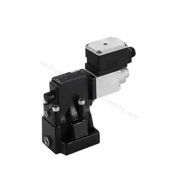
DBE/M(E) Series Proportional Pressure Relief Hydraulic Valve
Kā viens no hidraulisko cilindru ražotājiem, piegādātājiem un eksportētājiem, mēs piedāvājam hidrauliskos cilindrus un daudzus citus produktus.
Lūdzu, sazinieties ar mums, lai saņemtu sīkāku informāciju.
Pasts:sales@hydraulic-cylinders.net
Hidraulisko cilindru ražotājs, piegādātājs, eksportētājs.
DBE/M(E) Series Proportional Pressure Relief Hydraulic Valve
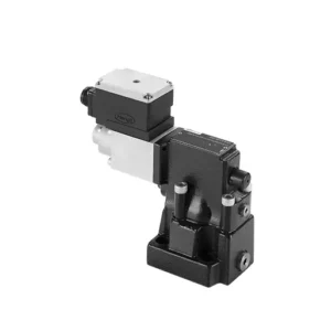
The DBE/M(E) series proportional pressure relief hydraulic valve is a state-of-the-art component designed to deliver precise pressure control in hydraulic systems. With its advanced proportional control technology, this valve ensures optimal performance, efficiency, and safety.
The DBE/M(E) series proportional pressure relief hydraulic valve empowers hydraulic systems with precise pressure control, enhanced efficiency, and equipment protection. With its advanced proportional control technology, this valve ensures optimal performance across various applications. By following the recommended usage methods and maintenance guidelines, you can maximize the benefits and reliability of the DBE/M(E) series valve, elevating the pressure control and overall performance of your hydraulic system. Upgrade your hydraulic setup today and experience superior pressure regulation with the DBE/M(E) series proportional pressure relief hydraulic valve.
DBE6X(E) Series Proportional Pressure Relief Hydraulic Valve Key Characteristics:
- Proportional Pressure Relief:
- The DBE/M(E) series valve offers precise and proportional pressure relief, allowing for dynamic control of hydraulic pressure.
- It ensures accurate pressure regulation in response to varying load conditions, preventing system overload and safeguarding hydraulic components.
- Uzlabota sistēmas efektivitāte:
- Šis vārsts nodrošina precīzu hidrauliskā spiediena kontroli, kā rezultātā tiek uzlabota sistēmas efektivitāte un samazināts enerģijas patēriņš.
- By maintaining the desired pressure levels, it minimizes pressure fluctuations, optimizes system performance, and reduces operational costs.
- Drošība un aprīkojuma aizsardzība:
- The DBE/M(E) series valve acts as a protective mechanism by limiting the pressure within the hydraulic system, safeguarding equipment and operators.
- Tas novērš pārmērīga spiediena palielināšanos, samazinot detaļu bojājumu, sistēmas kļūmju un iespējamu negadījumu risku.
- Proporcionālās vadības funkcionalitāte:
- With its proportional control technology, the DBE/M(E) series valve offers smooth and precise pressure adjustment.
- Tas nodrošina spiediena kontroli reāllaikā, nodrošinot nemanāmu integrāciju dažādās hidrauliskajās sistēmās un lietojumprogrammās.
DBE/M(E) Series Proportional Pressure Relief Hydraulic Valve Parameter:
| Vispārīgi | ||||
| Šķidrums | Minerāleļļa, kas piemērota NBR un FKM blīvējumiem | |||
| Fosfāta esteris FKM blīvējumam | ||||
| Šķidruma temperatūras diapazons | ℃ | -30 līdz +80 (NBR blīvējumi) | ||
| -20 līdz +80 (FKM blīvējumi) | ||||
| Viskozitātes diapazons | mm2/s | 2,8 līdz 380 | ||
| Piesārņojuma pakāpe | Maksimāli pieļaujamā šķidruma piesārņojuma pakāpe: 9. klase. NAS 1638 vai 20/18/15, ISO4406 | |||
| Maks. darba spiediens | 315 bāri | |||
| A, B un X porti | bārs | 50; 100; 200; 315 | ||
| Maks. iestatīšanas spiediens | bārs | Attiecībā uz plūsmu (Q) skatiet raksturlīknes | ||
| Min. iestatāmais spiediens | =Min. iestatāmais spiediens | |||
| Min. iestatāmais spiediens pie 0 komandas vērtības | Atsevišķi un bez spiediena tvertnēs | |||
| Atgriešanās eļļas spiediena ports Y | bārs | Spiediena iestatīšana | Spiediena diapazons zem maksimālā drošības spiediena | |
| Maksimālā spiediena drošība (bezgalīgi regulējama) | 50 bāri | 10-60+20 bārs | ||
| 100 bāri | 10-120+20 bārs | |||
| 200 bāri | 10-220+20 bārs | |||
| 315 bāri | 10-340+20 bārs | |||
| Maks. spiediena drošības iestatījuma nosacījums | Ja nominālais spiediens ir 50 bāri, starp 60 bāriem un 80 bāriem | |||
| Ja nominālais spiediens ir 100 bāri, starp 120 bāriem un 140 bāriem | ||||
| Ja nominālais spiediens ir 200 bāri, starp 220 bāriem un 240 bāriem | ||||
| Ja nominālais spiediens ir 315 bāri, starp 340 bāriem un 360 bāriem | ||||
| Izmērs | 10 | 25 | 32 | |
| Maks. plūsmas ātrums | 200 | 400 | 600 | |
| Pilota eļļa (pilota vārstam)) | L/min | 0,7 līdz 2 | ||
| Linearitāte | L/min | ±3,5% | ||
| Atkārtojamība | <±2% | |||
| Histerēze | ar vibroforu | bez vibroforta | ||
| ±1,5% P max (200 Hz, amplitūda 200 mAss) | ±4,5% P maks. | |||
| Pārslēgšanas laiks | 30~150ms (neatkarīgi no sistēmas) | |||
| Elektriskie dati | ||||
| Jauda | Līdzstrāva | |||
| Min. solenoīda strāva | mA | 100 | ||
| Maksimālā solenoīda strāva | mA | 800 | ||
| Spoles pretestība | 19,5 Ω pie 20 ℃, maksimālā siltuma vērtība: 28,8 Ω | |||
| Darba statuss | Nepārtraukts | |||
| Maks. apkārtējās vides temperatūras diapazons | +50 ℃ | |||
| Elektriskais pieslēgums | Spraudņa savienotājs atbilstoši DIN 43 650/2 +SL/PG11 | |||
| Izolācija saskaņā ar DIN 40 050 | IP65 | |||
| Pastiprinātājs | VT2000 | |||
DBE/M(E) Series Proportional Pressure Relief Hydraulic Valve Advantages:
• Izmanto apakšējās apakšplāksnes montāžai
• Uzstādīšanas virsma atbilst DIN24340 E un ISO 6264 standartiem
• Izmanto eļļas ceļa bloku uzstādīšanā
• Četri spiediena diapazoni
• Augstākā spiediena aizsardzības konstrukcija (pēc izvēles)
• Atbilstošs elektroniskais pastiprinātājs VT-2000 tipa (jāpasūta atsevišķi)
Usage Method Of DBE/M(E) Series Proportional Pressure Relief Hydraulic Valve:
- Sistēmas novērtēšana:
- Novērtējiet savu hidraulisko sistēmu un nosakiet īpašās spiediena kontroles prasības.
- Determine if the DBE/M(E) series valve is compatible with your system based on its pressure range, flow capacity, and other specifications.
- Vārsta izvēle:
- Choose the appropriate DBE/M(E) series valve variant based on your system parameters, pressure range, and flow requirements.
- Ņemiet vērā maksimālo spiediena novērtējumu, reakcijas laiku un ekspluatācijas apstākļus.
- Uzstādīšana:
- Rūpīgi ievērojiet ražotāja uzstādīšanas instrukcijas, nodrošinot pareizu izlīdzināšanu un drošu vārsta stiprinājumu.
- Pievienojiet vārstu hidrauliskajai sistēmai, nodrošinot savienojumus bez noplūdēm un pareizu plūsmas virziena izlīdzināšanu.
- Spiediena regulēšana:
- Utilize the proportional control signal or adjustment mechanism provided with the DBE/M(E) series valve to set the desired pressure relief level.
- Regulējiet vārstu pakāpeniski, uzraugot spiediena mērītāja rādījumus un sistēmas reakciju, lai panāktu precīzu spiediena kontroli.
Kā regulēt hidrauliskā spiediena samazināšanas vārstu?
Hidrauliskā spiediena samazināšanas vārsta regulēšana ļauj regulēt maksimālo spiedienu hidrauliskajā sistēmā. Tas ir svarīgi, lai saglabātu sistēmas integritāti un novērstu komponentu bojājumus. Šeit ir sniegta detalizēta instrukcija par hidrauliskā spiediena samazināšanas vārsta regulēšanu:
- Identificējiet spiediena samazināšanas vārstu:
- Atrodiet hidrauliskā spiediena samazināšanas vārstu savā sistēmā. Tas parasti ir novietots hidrauliskajā līnijā vai integrēts kolektora blokā.
- Izprotiet vārsta konstrukciju:
- Iepazīstieties ar spiediena samazināšanas vārsta, ar kuru strādājat, konkrēto konstrukciju. Dažādiem vārstiem var būt dažādi regulēšanas mehānismi, piemēram, poga, skrūve vai fiksācijas uzgrieznis.
- Nosakiet vēlamo spiediena iestatījumu:
- Novērtējiet savas hidrauliskās sistēmas prasības un nosakiet vēlamo maksimālo spiedienu. Ņemiet vērā sistēmas specifikācijas, slodzes apstākļus un drošības ierobežojumus.
- Sagatavojiet sistēmu:
- Pirms jebkādu regulējumu veikšanas izslēdziet hidraulisko sistēmu un samaziniet spiedienu, pārvietojot vadības sviras uz priekšu un atpakaļ vai ievērojot ražotāja ieteikto procedūru.
- Atrodiet regulēšanas mehānismu:
- Nosakiet spiediena samazināšanas vārsta regulēšanas mehānismu. Tā varētu būt poga, skrūve vai fiksācijas uzgrieznis, kas novietots uz vārsta korpusa vai blakus tam.
- Pielāgojiet vārstu:
- Ja vārstam ir poga vai rokturis, pagrieziet to pulksteņrādītāja virzienā, lai palielinātu spiediena samazināšanas iestatījumu, vai pretēji pulksteņrādītāja virzienam, lai to samazinātu. Ja vārstam ir skrūve, pagrieziet to pulksteņrādītāja virzienā, lai palielinātu zemi, vai pretēji pulksteņrādītāja virzienam, lai to nolaistu.
- Veikt pakāpeniskas korekcijas:
- Regulējot spiediena samazināšanas vārstu, veiciet nelielas, pakāpeniskas izmaiņas, lai izvairītos no pēkšņām vai krasām spiediena svārstībām. Tas ļauj precīzi noregulēt sistēmu un novērst iespējamus bojājumus.
- Ievērojiet sistēmu:
- Veicot katru regulēšanu, novērojiet hidrauliskās sistēmas spiediena mērītāju vai indikatoru, lai redzētu izmaiņu ietekmi. Pārliecinieties, vai spiediens paliek vēlamajā diapazonā.
- Pārbaude un verifikācija:
- Pakāpeniski palieliniet sistēmas spiedienu un uzraugiet spiediena samazināšanas vārsta reakciju. Pārliecinieties, ka tas mazina slodzi, kad tiek sasniegts maksimālais iestatītais spiediens, un uztur vēlamo maksimālo spiedienu.
- Regulēšanas fiksēšana:
- Kad esat sasniedzis vēlamo spiediena iestatījumu, nostipriniet regulēšanas mehānismu, lai novērstu nejaušas izmaiņas. Dažiem vārstiem var būt bloķēšanas uzgrieznis vai regulēšanas skrūve, ko var pievilkt, lai noturētu regulējumu vietā.
- Dokumentējiet korekciju:
- Saglabājiet pielāgotā spiediena samazināšanas iestatījuma ierakstu turpmākai uzziņai un apkopes vajadzībām. Šī dokumentācija palīdzēs nodrošināt konsekvenci un atvieglos problēmu novēršanu.
Rūpnīcas iespējas un jauda:
(1) Montāža
Mums ir pirmklasīga neatkarīga pētniecības un attīstības montāžas platforma. Hidraulisko cilindru ražošanas darbnīcā ir četras pusautomātiskas pacelšanas cilindru montāžas līnijas un viena automātiskā slīpuma cilindru montāžas līnija ar projektēto gada ražošanas jaudu 1 miljons vienību. Speciālo cilindru darbnīca ir aprīkota ar dažādu specifikāciju pusautomātisku tīrīšanas montāžas sistēmu ar projektēto gada ražošanas jaudu 200 000 vienību un aprīkota ar slavenām CNC apstrādes iekārtām, apstrādes centru, augstas precizitātes cilindru apstrādes speciālo aprīkojumu, robotizētu metināšanas iekārtu, automātisku tīrīšanas iekārtu, automātisku cilindru montāžas iekārtu un automātisku krāsošanas ražošanas līniju. Esošais kritiskais aprīkojums ir vairāk nekā 300 komplektu (komplektu). Optimāla iekārtu resursu sadale un efektīva izmantošana nodrošina produktu precizitātes prasības un apmierina produktu augstās kvalitātes prasības.


(2) Apstrāde
Apstrādes cehs ir aprīkots ar pielāgotu slīpo sliežu virpošanas centru, apstrādes centru, ātrgaitas asināšanas mašīnu, metināšanas robotu un citu saistītu aprīkojumu, kas var apstrādāt cilindriskas caurules ar maksimālo iekšējo diametru 400 mm un maksimālo garumu 6 metri.

(3) Metināšana

(4) Krāsošana un pārklāšana
Ar mazām un vidēja izmēra cilindriskām automātiskām ūdens bāzes krāsu pārklāšanas līnijām, lai panāktu automātisku robotu iekraušanu un izkraušanu un automātisku izsmidzināšanu, projektētā jauda ir 4000 gabali maiņā;
Mums ir arī pusautomātiska krāsu ražošanas līnija lieliem baloniem, ko darbina ķēdes piedziņa, ar 60 kastu konstrukcijas jaudu vienā maiņā.


(5) Testēšana
Mums ir augstākās klases pārbaudes iekārtas un testēšanas stendi, lai nodrošinātu, ka balona veiktspēja atbilst prasībām.

Mēs esam viens no labākajiem hidraulisko cilindru ražotājiem. Mēs varam piedāvāt visaptverošus hidrauliskos cilindrus. Mēs nodrošinām arī atbilstošus lauksaimniecības pārnesumkārbas. Mēs esam eksportējuši savus produktus klientiem visā pasaulē un esam ieguvuši labu reputāciju, pateicoties mūsu izcilajai produktu kvalitātei un pēcpārdošanas servisam. Mēs aicinām klientus no valsts un ārvalstīm sazināties ar mums, lai risinātu biznesa sarunas, apmainītos ar informāciju un... sadarboties ar mums!
Hidrauliskā cilindra pielietojums:
