30SD10-21 Solenoid Directional Valve
Som en av produsentene, leverandørene og eksportørene av mekaniske produkter tilbyr vi hydrauliske sylindere og mange andre produkter.
Ta kontakt med oss for mer informasjon.
Post:sales@hydraulic-cylinders.net
Produsent, leverandør og eksportør av hydrauliske sylindere.
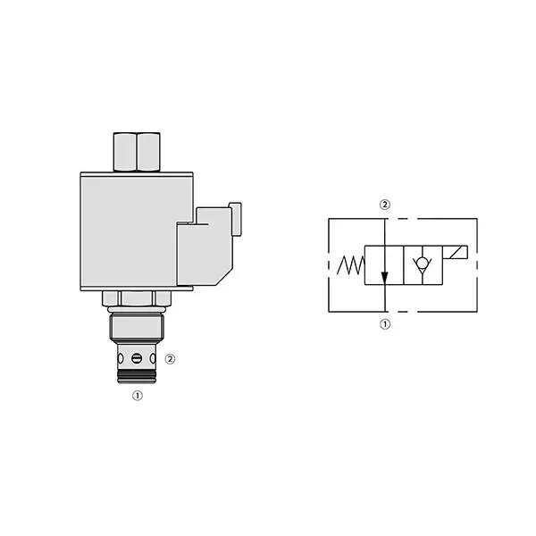
30SD10-21 Solenoid Directional Valve

The 30SD10-21 solenoid directional valve is a high-performance component that optimizes fluid control in various industrial applications. With its advanced features, precise operation, and reliable performance, this solenoid valve offers exceptional functionality and efficiency, making it a valuable asset for fluid control systems. From manufacturing to automation, the 30SD10-21 solenoid directional valve delivers precise and reliable fluid control, empowering industries to enhance productivity and streamline operations.
The 30SD10-21 solenoid directional valve is a versatile and reliable component that enhances fluid control efficiency in industrial applications. With its robust construction, precise fluid control, versatility, and reliable performance, this solenoid valve offers exceptional functionality, ensuring optimal operations and increased productivity. By incorporating the 30SD10-21 solenoid directional valve into fluid control systems, industries can achieve enhanced efficiency, accuracy, and system performance. Invest in this advanced solenoid valve to streamline your fluid control processes, improve productivity, and gain a competitive edge in your industry.
Kjennetegn på 30SD10-21 magnetisk retningsventil:
- Robust Construction: The 30SD10-21 solenoid directional valve is built robustly, ensuring durability and longevity even in demanding environments. Its sturdy construction allows it to withstand high pressures, temperature variations, and harsh conditions, providing consistent and reliable performance.
- Precise Fluid Control: This solenoid valve offers precise control over fluid flow, allowing for accurate regulation and efficient management of liquids or gases. With its responsive solenoid mechanism, the valve enables quick and reliable switching between different flow paths, ensuring precise control and minimizing disruptions.
- Versatile Functionality: The 30SD10-21 solenoid directional valve offers versatile functionality, making it suitable for various applications. Whether directional control, on/off switch, or pressure regulation, this valve can be tailored to meet specific system requirements, providing flexibility and adaptability in fluid control systems.
- Reliable Performance: This solenoid valve is designed for reliable performance, ensuring consistent and efficient fluid control operations. Its high-quality components and precision engineering contribute to its reliability, allowing for smooth and trouble-free operation even in critical applications.
30SD10-21 Solenoid Directional Valve Parameter:
| Nominelt trykk | 241 bar (3500 psi) | |
| Toppstrøm | 56.8 L/min (15 gpm) ; See performance chart | |
| Væske | Mineralbaserte eller syntetiske stoffer med smørende egenskaper | |
| Væsketemperaturområde ℃ | -54 til 107 ℃ (polyuretanpakninger) | |
| -40 til 100 ℃ (Buna N-tetninger) | ||
| -26 til 204 ℃ (fluorkarbontetninger) | ||
| Viskositetsområde | 7,4 til 420 mm2/s | |
| Grad av forurensning | Minimum forurensningsnivå er ISO4406 nivå 18/16/13, og nivå 15/13/11 anbefales for å forlenge levetiden. | |
| Intern lekkasje | ≤ 0.15 mL/min (3 drops /min) @241 bar | |
| Hulrom | VC10-2 | |
| Spolebelastningsklassifisering | Kontinuerlig fra 85% til 115% nominell spenning | |
| Innledende spolestrømtrekk ved 20 ℃ | E-spole | 1,7 A ved 12 VDC; 0,85 A ved 24 VDC |
| D-spole | 1,67 A ved 12 VDC; 0,83 A ved 24 VDC | |
| Minimum inntrekksspenning | 85% of nominal at 241 bar | |
30SD10-21 Solenoid Directional Valve Advantages:
• Spole for kontinuerlig drift
• Effektiv våtarmaturkonstruksjon
• Patroner kan byttes ut med spenning
• Valgfrie vanntette e-spoler med IP69K-klassifisering
• Felles hulrom i industrien
• Herdede deler for lang levetid og lav lekkasje
Usage Method Of 30SD10-21 Solenoid Directional Valve:
Installasjon:
- Follow the manufacturer’s instructions for properly installing the 30SD10-21 Solenoid Directional Valve.
- Ensure accurate alignment and connection to the fluid control system, using appropriate fittings and seals to maintain a leak-free operation.
Elektriske tilkoblinger:
- Connect the solenoid valve to the power supply, adhering to the specified voltage and electrical requirements.
- Ensure proper wiring and insulation to ensure safe and reliable electrical operation.
Fluid Flow Direction:
- Determine the desired fluid flow direction based on the application requirements.
- The 30SD10-21 solenoid directional valve provides various ports and positions for inlet, outlet, and exhaust. Refer to the product documentation for correct port connections.
Control Signal:
- Connect the control signal, whether electrical or pneumatic, to the solenoid valve to activate its switching mechanism.
- Ensure that the control signal is compatible with the valve’s specifications and operating parameters.
How To Hook Up A Hydraulic Flow Control Valve?
To hook up a hydraulic flow control valve, follow these steps:
- Identify Valve Type: Determine the specific type of flow control valve you are working with. Common types include needle valves, adjustable flow control valves, or pressure-compensated flow control valves. Ensure that the valve is suitable for your application and compatible with your hydraulic system.
- Gather Required Tools and Materials: Collect the necessary tools and materials, including appropriate hydraulic fittings, adapters, hoses, and wrenches.
- Klargjør det hydrauliske systemet: Shut down the hydraulic system and relieve any pressure in the system by activating the relief valve or retracting any hydraulic cylinders. This step is crucial for safety.
- Identify Flow Direction: Identify the flow direction in your hydraulic system. Typically, the flow direction is indicated by arrows on the hydraulic components. Ensure that you understand the correct flow direction before proceeding.
- Locate Installation Point: Determine the optimal location to install the flow control valve in your hydraulic system. Consider factors such as accessibility, proximity to the actuator or hydraulic component, and ease of adjustment.
- Monter ventilen: Securely mount the flow control valve in the chosen location using appropriate brackets or clamps. Ensure the valve is positioned correctly, aligning the inlet and outlet ports with the flow direction.
- Koble til innløps- og utløpsportene: Attach hydraulic hoses or tubing to the inlet and outlet ports of the flow control valve. Use suitable hydraulic fittings and adapters to create a leak-free connection. Tighten the connections using wrenches to ensure a secure fit, but avoid over-tightening.
- Adjust the Flow Control: Depending on the type of flow control valve, it may have adjustable features such as a needle valve or a flow control knob. Adjust the valve according to your desired flow rate or speed. Refer to the manufacturer’s instructions for specific adjustment procedures.
- Test systemet: Once the flow control valve is installed and adjusted, slowly restore hydraulic system pressure. Test the system to ensure that the flow control valve is functioning correctly. Monitor the flow rate or speed of the hydraulic actuator to verify that it is within the desired range.
- Fine-tune and Monitor: Adjust the flow control valve to achieve the desired flow rate or speed. Regularly monitor the hydraulic system for leaks, pressure inconsistencies, or unusual behavior.
Fabrikkens kapasitet og kapasitet:
(1) Montering
Vi har en førsteklasses uavhengig forsknings- og utviklingsplattform for montering. Verkstedet for produksjon av hydrauliske sylindere har fire halvautomatiske monteringslinjer for løftesylindere og én automatisk monteringslinje for vippesylindere, med en årlig produksjonskapasitet på 1 million enheter. Spesialsylinderverkstedet er utstyrt med ulike spesifikasjoner for et halvautomatisk rengjøringsmonteringssystem med en årlig produksjonskapasitet på 200 000 enheter, og er utstyrt med kjent CNC-maskineringsutstyr, et maskineringssenter, spesialutstyr for høypresisjons sylinderbehandling, en robotsveisemaskin, en automatisk rengjøringsmaskin, en automatisk sylindermonteringsmaskin og en automatisk produksjonslinje for lakkering. Vi har mer enn 300 sett (sett) av kritisk utstyr. Optimal allokering og effektiv bruk av utstyrsressurser sikrer nøyaktighetskravene til produktene og oppfyller produktenes høye kvalitetsbehov.


(2) Maskinering
Maskineringsverkstedet er utstyrt med et spesialtilpasset dreiesenter for skrå skinner, maskineringssenter, høyhastighets honemaskin, sveiserobot og annet relatert utstyr, som kan håndtere bearbeiding av sylinderrør med en maksimal indre diameter på 400 mm og en maksimal lengde på 6 meter.

(3) Sveising

(4) Maling og belegg
Med små og mellomstore sylinderautomatiske vannbaserte malingsbeleggslinjer, for å oppnå automatisk robotlasting og -lossing og automatisk sprøyting, er den designede kapasiteten 4000 stykker per skift;
Vi har også en halvautomatisk produksjonslinje for maling for store sylindere drevet av en kabelkjede, med en designkapasitet på 60 kasser per skift.


(5) Testing
Vi har førsteklasses inspeksjonsfasiliteter og testbenker for å sikre at sylinderens ytelse oppfyller kravene.

Vi er en av de beste produsentene av hydrauliske sylindere. Vi kan tilby et omfattende utvalg av hydrauliske sylindere. Vi tilbyr også tilsvarende landbruksgirkasserVi har eksportert produktene våre til kunder over hele verden og opparbeidet oss et godt rykte på grunn av vår overlegne produktkvalitet og ettersalgsservice. Vi ønsker kunder i inn- og utland velkommen til å kontakte oss for å forhandle om forretninger, utveksle informasjon og samarbeide med oss!
Hydraulisk sylinderapplikasjon:
