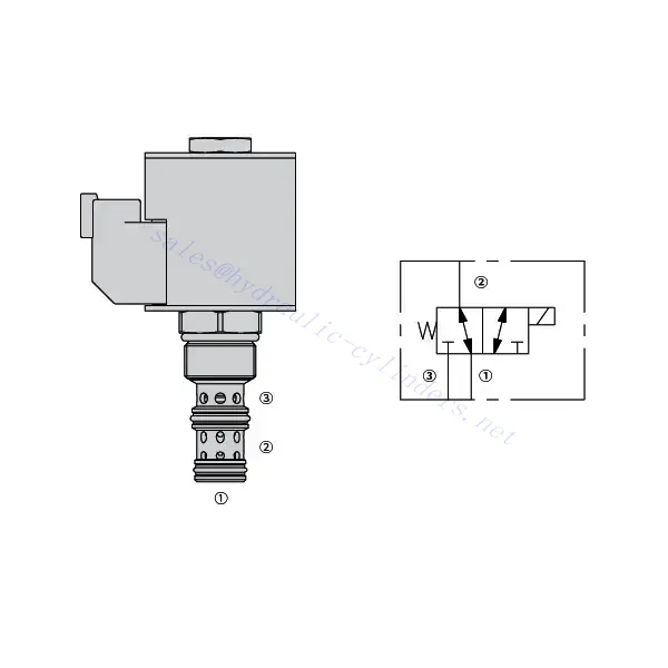
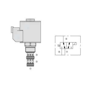
30SD10-34 Solenoid Directional Valve
Som en av produsentene, leverandørene og eksportørene av mekaniske produkter tilbyr vi hydrauliske sylindere og mange andre produkter.
Ta kontakt med oss for mer informasjon.
Post:sales@hydraulic-cylinders.net
Produsent, leverandør og eksportør av hydrauliske sylindere.
30SD10-34 Solenoid Directional Valve
The 30SD10-34 solenoid directional valve is a cutting-edge industrial component designed to provide precise and reliable fluid control in a wide range of applications. With its advanced features, durable construction, and user-friendly design, this solenoid directional valve offers enhanced performance and efficiency.
The 30SD10-34 solenoid directional valve is a reliable and versatile component that offers precise fluid control in industrial applications. Its robust construction, precision control, and reliable performance make it an ideal choice for enhancing the efficiency and productivity of your fluid control systems. By following the recommended usage methods and maintenance guidelines, you can ensure optimal performance and longevity of the 30SD10-34 solenoid directional valve in your industrial operations.
30SD10-34 Solenoid Directional Valve Characteristics:
- Robust Construction: The 30SD10-34 solenoid directional valve is built with high-quality materials and meticulous craftsmanship, ensuring durability and longevity. Its robust construction allows it to withstand demanding industrial environments, providing reliable performance even under harsh conditions.
- Versatile Functionality: This solenoid directional valve offers versatile functionality, making it suitable for various applications. It effectively controls the direction of fluid flow, allowing precise and efficient operation in different industrial systems.
- Precision Control: With exceptional precision, the 30SD10-34 solenoid directional valve enables accurate control over fluid flow. It allows for precise regulation and adjustment of fluid direction and pressure, ensuring optimal performance and efficiency in industrial processes.
- Reliable Performance: This solenoid directional valve delivers reliable performance, minimizing the risk of system failures or interruptions. It operates dependably, contributing to increased productivity and reduced downtime in industrial operations.
30SD10-34 Solenoid Directional Valve Parameter:
| Nominelt trykk | 207 bar (3000 psi) | |
| Bevistrykk | 350 bar (5075 psi) | |
| Toppstrøm | 22.7 L/min (6 gpm) | |
| Væske | Mineralbaserte eller syntetiske stoffer med smørende egenskaper | |
| Temperature range ℃ | -54 til 107 ℃ (polyuretan-tetninger) | |
| -40 til 100 ℃ (Buna N-tetninger) | ||
| -26 til 204 ℃ (fluorkarbontetninger) | ||
| Viskositetsområde | 7,4 til 420 mm2/s | |
| Grad av forurensning | Minimum forurensningsnivå er ISO4406 nivå 20/18/14, og nivå 17/15/13 anbefales for å forlenge levetiden. | |
| Intern lekkasje | ≤ 115 mL/min@207bar | |
| Hulrom | VC10-3 | |
| Spolebelastningsklassifisering | Kontinuerlig fra 85% til 115% nominell spenning | |
| Response time | First indication of change of state with 100% voltage supplied at80% of nominal flow rating:Energized: 60 msec. ; De-energized: 10 msec. | |
| Innledende spolestrømtrekk ved 20 ℃ | E-spole | 1,7 A ved 12 VDC; 0,85 A ved 24 VDC |
| D-spole | 1,67 A ved 12 VDC; 0,83 A ved 24 VDC | |
| Minimum inntrekksspenning | 85% av nominell ved 207 bar | |
30SD10-34 Solenoid Directional Valve Advantages:
• Spole for kontinuerlig drift
• Effektiv våtarmaturkonstruksjon
• Patroner kan byttes ut med spenning
• Valgfrie vanntette e-spoler med IP69K-klassifisering
• All ports may be fully pressurized
• Felles hulrom i industrien
• Herdede deler for lang levetid og lav lekkasje
Usage Method Of 30SD10-34 Solenoid Directional Valve:
- Integration into System: Integrate the 30SD10-34 solenoid directional valve into the fluid control system following the manufacturer’s guidelines and specifications. Ensure proper alignment and connection between the valve and other system components to achieve optimal performance.
- Electrical Connection: Establish a secure electrical connection for the solenoid directional valve. Refer to the provided wiring diagram and ensure correct polarity to prevent any electrical malfunctions. Follow safety guidelines when working with electrical connections.
- Fluid Flow Direction Control: Utilize the solenoid directional valve to control the direction of fluid flow. The valve is typically equipped with a lever or actuator for manual adjustment. Alternatively, it can be integrated into an automated control system for remote operation.
- Pressure Adjustment: Employ the solenoid directional valve to regulate fluid pressure within the system. By adjusting the valve’s settings, you can achieve the desired pressure levels for optimal performance and efficiency.
How To Plumb Auto Cycle Hydraulic Valve?
Plumbing an auto-cycle hydraulic valve requires careful attention to ensure proper installation and functionality. Follow these steps to plumb an auto-cycle hydraulic valve effectively:
- Samle nødvendige verktøy og materialer: Before you begin, make sure you have all the required tools and materials, including hydraulic hoses, fittings, adapters, Teflon tape, wrenches, and a hydraulic fluid reservoir.
- Identify The Valve Ports: Examine the auto-cycle hydraulic valve to identify the different ports. Typically, there will be inlet ports, outlet ports, and possibly additional ports for pressure relief or auxiliary functions.
- Determine The Hydraulic Fluid Flow Direction: Determine the desired flow direction of the hydraulic fluid through the valve. This information is crucial for correctly connecting the inlet and outlet ports.
- Install Fittings And Adapters: Install the appropriate fittings and adapters onto the valve ports. Ensure they are tightened securely, but be careful not to overtighten and damage the threads.
- Apply Teflon Tape: Wrap Teflon tape around the threads of the fittings and adapters. This helps create a tight seal and prevents leaks.
- Connect Hydraulic Hoses: Attach hydraulic hoses to the fittings and adapters on the valve ports. Ensure the hoses are suitable for the hydraulic system’s pressure rating and are of the correct length.
- Secure Hose Connections: Use hose clamps or other suitable methods to secure the hydraulic hoses to the fittings. This prevents the hoses from coming loose during operation.
- Route The Hydraulic hoses: Carefully route the hydraulic hoses to connect the auto-cycle hydraulic valve to the hydraulic fluid reservoir and other hydraulic components, such as cylinders or motors. Avoid sharp bends or kinks in the hoses that could restrict fluid flow.
- Sjekk for lekkasjer: Once all connections are made, check for leaks. Start by slowly pressurizing the system and inspecting each connection point. If you notice any leaks, tighten the fittings or replace faulty components as necessary.
- Fill The Hydraulic Fluid Reservoir: Fill the hydraulic fluid reservoir with the recommended type and quantity of hydraulic fluid. Refer to the manufacturer’s guidelines for the appropriate fluid specifications.
- Bleed Air From The System: B bleed any air trapped in the hydraulic system to ensure proper operation. Follow the manufacturer’s instructions for bleeding procedures, which typically involve cycling the design and opening bleed valves.
- Test The System: With the plumbing complete, test the auto-cycle hydraulic valve and the overall system’s performance. Verify that the valve functions as intended and that fluid flow is smooth and consistent.
Fabrikkens kapasitet og kapasitet:
(1) Montering
Vi har en førsteklasses uavhengig forsknings- og utviklingsplattform for montering. Verkstedet for produksjon av hydrauliske sylindere har fire halvautomatiske monteringslinjer for løftesylindere og én automatisk monteringslinje for vippesylindere, med en årlig produksjonskapasitet på 1 million enheter. Spesialsylinderverkstedet er utstyrt med ulike spesifikasjoner for et halvautomatisk rengjøringsmonteringssystem med en årlig produksjonskapasitet på 200 000 enheter, og er utstyrt med kjent CNC-maskineringsutstyr, et maskineringssenter, spesialutstyr for høypresisjons sylinderbehandling, en robotsveisemaskin, en automatisk rengjøringsmaskin, en automatisk sylindermonteringsmaskin og en automatisk produksjonslinje for lakkering. Vi har mer enn 300 sett (sett) av kritisk utstyr. Optimal allokering og effektiv bruk av utstyrsressurser sikrer nøyaktighetskravene til produktene og oppfyller produktenes høye kvalitetsbehov.


(2) Maskinering
Maskineringsverkstedet er utstyrt med et spesialtilpasset dreiesenter for skrå skinner, maskineringssenter, høyhastighets honemaskin, sveiserobot og annet relatert utstyr, som kan håndtere bearbeiding av sylinderrør med en maksimal indre diameter på 400 mm og en maksimal lengde på 6 meter.

(3) Sveising

(4) Maling og belegg
Med små og mellomstore sylinderautomatiske vannbaserte malingsbeleggslinjer, for å oppnå automatisk robotlasting og -lossing og automatisk sprøyting, er den designede kapasiteten 4000 stykker per skift;
Vi har også en halvautomatisk produksjonslinje for maling for store sylindere drevet av en kabelkjede, med en designkapasitet på 60 kasser per skift.


(5) Testing
Vi har førsteklasses inspeksjonsfasiliteter og testbenker for å sikre at sylinderens ytelse oppfyller kravene.

Vi er en av de beste produsentene av hydrauliske sylindere. Vi kan tilby et omfattende utvalg av hydrauliske sylindere. Vi tilbyr også tilsvarende landbruksgirkasserVi har eksportert produktene våre til kunder over hele verden og opparbeidet oss et godt rykte på grunn av vår overlegne produktkvalitet og ettersalgsservice. Vi ønsker kunder i inn- og utland velkommen til å kontakte oss for å forhandle om forretninger, utveksle informasjon og samarbeide med oss!
Hydraulisk sylinderapplikasjon:
