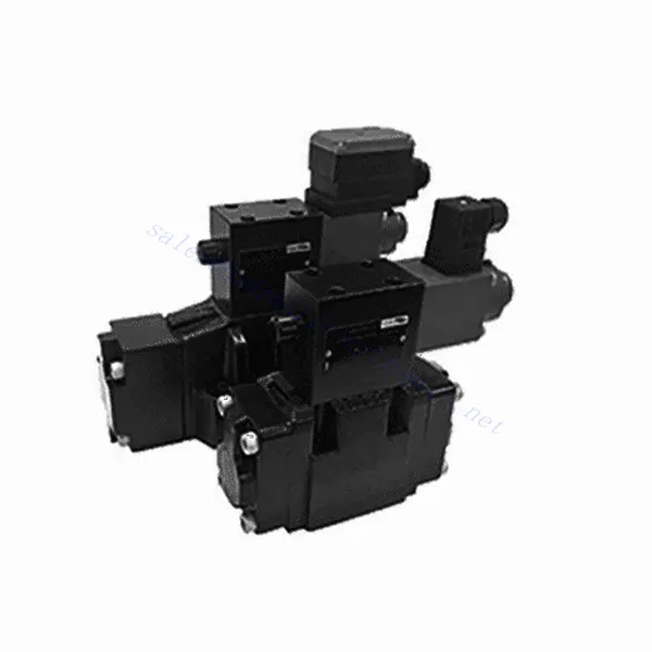
3DRE/M(E) Series 3-way Pilot Operated Proportional Pressure Reducing Hydraulic Valve
Som en av produsentene, leverandørene og eksportørene av mekaniske produkter tilbyr vi hydrauliske sylindere og mange andre produkter.
Ta kontakt med oss for mer informasjon.
Post:sales@hydraulic-cylinders.net
Produsent, leverandør og eksportør av hydrauliske sylindere.
3DRE/M(E) Series 3-way Pilot Operated Proportional Pressure Reducing Hydraulic Valve
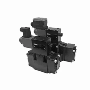
The 3DRE/M(E) series 3-way pilot-operated proportional pressure-reducing hydraulic valve is a cutting-edge hydraulic component designed to deliver accurate pressure control in hydraulic systems. With its advanced pilot-operated proportional control technology, this valve ensures precise regulation, efficient performance, and reliable operation.
The 3DRE/M(E) series 3-way proportional pressure-reducing hydraulic valve empowers hydraulic systems with precise pressure control, efficiency, and reliable performance. With its advanced proportional control technology and 3-way configuration, this valve offers versatility and flexibility in pressure regulation across different hydraulic circuits. By following the recommended usage methods and maintenance guidelines, you can maximize the benefits and longevity of the 3DRE/M(E) series valve, optimizing pressure control and overall performance in your hydraulic system. Upgrade your hydraulic setup today and experience superior pressure regulation with the 3DRE/M(E) series 3-way proportional pressure-reducing hydraulic valve.
3DRE/M(E) Series 3-way Pilot Operated Proportional Pressure Reducing Hydraulic Valve Key Characteristics:
- Proportional Pressure Control:
- The 3DRE/M(E) series valve offers precise and proportional pressure control, enabling dynamic adjustment of hydraulic pressure levels.
- This feature ensures accurate pressure regulation, maintaining a consistent and safe pressure within the hydraulic system.
- Pilotdrevet design:
- With its pilot-operated design, the valve delivers enhanced precision and responsiveness in pressure control.
- It utilizes a pilot valve to modulate the main valve, allowing for precise adjustments and improved control over pressure reduction.
- 3-way Configuration:
- The 3DRE/M(E) series valve features a versatile 3-way configuration, providing flexibility in controlling pressure across different hydraulic circuits.
- It allows for simultaneous pressure reduction in one circuit while supplying pressure to another course.
- Effektiv ytelse:
- By utilizing advanced proportional control technology, the valve ensures efficient performance, optimizing energy usage and reducing operational costs.
- It minimizes pressure fluctuations, enhancing system efficiency and contributing to overall productivity.
3DRE/M(E) Series 3-way Pilot Operated Proportional Pressure Reducing Hydraulic Valve Parameter:
| Hydraulisk | ||||||||
| Installasjonsposisjon | valgfritt, helst horisontalt | |||||||
| Størrelse | 6 | 10 | ||||||
| Vekt | 4WRA…L2X | kg | 2 | 6.6 | ||||
| 4WRAE…L2X | 2.2 | 6.8 | ||||||
| Nominell strømningsmengde qnom, når Δp = 10 bar | l/min | 7, 15, 26 | 30,60 | |||||
| Hysterese | % | ≤5 | ||||||
| Repeterbarhet | % | ≤1 | ||||||
| Responsfølsomhet | % | ≤0,5 | ||||||
| Maks. driftstrykk | Portens ABP | bar | 315 | |||||
| Port T | bar | 210 | ||||||
| Væske | Mineralolje egnet for NBR- og FKM-tetninger | |||||||
| Fosfatester for FKM-tetning | ||||||||
| Væsketemperaturområde | 4WRA…L2X | ℃ | -20 ℃ til 70 ℃ (-4 °F til 158 °F) | |||||
| 4WRAE…L2X | ℃ | -20 ℃ til 50 ℃ (-4° F til 122° F) | ||||||
| Viskositetsområde | mm²/s | 20 til 380 (helst 30 til 46) | ||||||
| Grad av forurensning | NAS1638 klasse 9 eller ISO 4406 klasse 20/18/15 | |||||||
| Elektriske data | ||||||||
| 1) solenoid | ||||||||
| Spenningstype | DC | |||||||
| Kommandoverdisignal | ±10V eller 4~20mA | |||||||
| Maks. strøm per solenoid | EN | 2.5 | 1.5 | 0.8 | ||||
| Spolemotstand | Kald verdi | Ω | 2 | 4.8 | 19.5 | |||
| Maks. varm verdi | 3 | 7.2 | 28.8 | |||||
| Plikt | % | ED100% | ||||||
| Spoletemperatur | ℃ | 150 | ||||||
| Ventilbeskyttelse i henhold til EN 60529 | IP65 | |||||||
| 2) Kontrollelektronikk | ||||||||
| Forsterker | 4WRA…L2X | VT-VSPA2-L2X | ||||||
| 4WRAE…L2X | Integrert i ventilen (OBE) | |||||||
| Driftsspenning | Nominell spenning | VDC | 24 | |||||
| Nedre grenseverdi | V | 21/22 (4WRA), 19 (4WRAE) | ||||||
| Øvre grenseverdi | V | 35 | ||||||
| Forsterkerens strømforbruk | Imax | EN | <1,8 | |||||
| Imax | EN | 3 | ||||||
3DREP(E) Series 3-way Proportional Pressure Reducing Hydraulic Valve Advantages:
• The pilot-operated relief valve is used for the pressure reduction from P to A and the overflow function from A to T.
• Used for bottom sub-plate mounting, driven by proportional solenoid.
• The mounting surface is in accordance with DIN24 340, type A, ISO4401 and CETOP-RP 121H
• The maximum safety pressure is available for selection.
• Spool spring alignmentalignment
• 3DRE electronic controller: european card specification amplifier VT-VSPA1-1/VT-VSPD-1
• Set point the pressure characteristic curve is linear
• 3DRE(M)E series integrated electronic controller
• Setting value caused by manufacturing error-the deviation of the pressure characteristic curve is small
• The slope of the pressure increase and decrease can be adjusted independently
Usage Method Of 3DREP(E) Series 3-way Proportional Pressure Reducing Hydraulic Valve:
- Systemevaluering:
- Evaluate your hydraulic system and identify the specific pressure control requirements for each circuit.
- Determine if the 3DRE/M(E) series valve is suitable based on its pressure range, flow capacity, and compatibility with your system.
- Ventilvalg:
- Select the appropriate variant of the 3DRE/M(E) series valve based on your system parameters, pressure range, and flow requirements.
- Consider maximum pressure rating, response time, and operational conditions.
- Installasjon:
- Følg produsentens installasjonsinstruksjoner nøye, og sørg for riktig justering og sikker montering av ventilen.
- Koble ventilen til det hydrauliske systemet. Sørg for lekkasjefrie tilkoblinger og riktig justering av strømningsretningen.
- Trykkjustering:
- Utilize the pilot valve control mechanism provided with the 3DRE/M(E) series valve to adjust the desired pressure reduction level for each circuit.
- Gradually adjust the pilot valve control to achieve the desired pressure control, monitoring the pressure gauge readings and system response.
How To Adjust Hydraulic Valves?
Adjusting hydraulic valves is a crucial task to ensure proper flow control and system performance in hydraulic applications. Here’s a step-by-step guide on how to adjust hydraulic valves:
- Identifiser ventilen:
- Determine the type of hydraulic valve you need to adjust: pressure relief valve, flow control valve, directional control valve, or any other type.
- Locate the valve within your hydraulic system. It can be positioned near the pump, in the control valve manifold, or within specific hydraulic components.
- Samle de nødvendige verktøyene:
- Before starting the adjustment process, gather the required tools, such as an adjustable wrench, a screwdriver, a pressure gauge (if applicable), and any specialized tools recommended by the valve manufacturer.
- Understand the Valve Function:
- Familiarize yourself with the purpose and function of the valve you are adjusting. Refer to the valve’s technical documentation or consult the manufacturer’s guidelines for specific details.
- Determine the Desired Setting:
- Identify the desired setting or parameter you want to achieve by adjusting the valve. This could be pressure, flow rate, direction, or any other adjustable parameter based on the valve type.
- Preliminary Checks:
- Ensure that the hydraulic system is depressurized before attempting any adjustments. This can be done by shutting down the system and relieving residual pressure through appropriate valves.
- Access the Adjustment Mechanism:
- Locate the adjustment mechanism on the valve. It can be a set screw, locknut, knob, or other similar devices depending on the valve type.
- Some valves may require removing a protective cap or cover to access the adjustment mechanism.
- Make Incremental Adjustments:
- Using the appropriate tool, make small incremental adjustments to the valve according to the desired setting.
- Follow the manufacturer’s guidelines to determine the direction (clockwise or counterclockwise) and the amount of adjustment required.
- Make gradual adjustments and periodically check the system’s response to ensure you are moving in the desired direction.
- Test and Monitor:
- After each adjustment, activate the hydraulic system and observe its performance.
- Use appropriate measurement tools (pressure gauge, flow meter, etc.) to verify that the valve is operating within the desired range.
- Monitor the system for any abnormalities or unexpected behavior. If necessary, make further adjustments to fine-tune the valve setting.
- Lock the Adjustment (if applicable):
- Once you achieve the desired setting, secure the adjustment mechanism to prevent unintended changes.
- This can be done by tightening a locknut, securing a set screw, or using any other method recommended by the valve manufacturer.
Fabrikkens kapasitet og kapasitet:
(1) Montering
Vi har en førsteklasses uavhengig forsknings- og utviklingsplattform for montering. Verkstedet for produksjon av hydrauliske sylindere har fire halvautomatiske monteringslinjer for løftesylindere og én automatisk monteringslinje for vippesylindere, med en årlig produksjonskapasitet på 1 million enheter. Spesialsylinderverkstedet er utstyrt med ulike spesifikasjoner for et halvautomatisk rengjøringsmonteringssystem med en årlig produksjonskapasitet på 200 000 enheter, og er utstyrt med kjent CNC-maskineringsutstyr, et maskineringssenter, spesialutstyr for høypresisjons sylinderbehandling, en robotsveisemaskin, en automatisk rengjøringsmaskin, en automatisk sylindermonteringsmaskin og en automatisk produksjonslinje for lakkering. Vi har mer enn 300 sett (sett) av kritisk utstyr. Optimal allokering og effektiv bruk av utstyrsressurser sikrer nøyaktighetskravene til produktene og oppfyller produktenes høye kvalitetsbehov.


(2) Maskinering
Maskineringsverkstedet er utstyrt med et spesialtilpasset dreiesenter for skrå skinner, maskineringssenter, høyhastighets honemaskin, sveiserobot og annet relatert utstyr, som kan håndtere bearbeiding av sylinderrør med en maksimal indre diameter på 400 mm og en maksimal lengde på 6 meter.

(3) Sveising

(4) Maling og belegg
Med små og mellomstore sylinderautomatiske vannbaserte malingsbeleggslinjer, for å oppnå automatisk robotlasting og -lossing og automatisk sprøyting, er den designede kapasiteten 4000 stykker per skift;
Vi har også en halvautomatisk produksjonslinje for maling for store sylindere drevet av en kabelkjede, med en designkapasitet på 60 kasser per skift.


(5) Testing
Vi har førsteklasses inspeksjonsfasiliteter og testbenker for å sikre at sylinderens ytelse oppfyller kravene.

Vi er en av de beste produsentene av hydrauliske sylindere. Vi kan tilby et omfattende utvalg av hydrauliske sylindere. Vi tilbyr også tilsvarende landbruksgirkasserVi har eksportert produktene våre til kunder over hele verden og opparbeidet oss et godt rykte på grunn av vår overlegne produktkvalitet og ettersalgsservice. Vi ønsker kunder i inn- og utland velkommen til å kontakte oss for å forhandle om forretninger, utveksle informasjon og samarbeide med oss!
Hydraulisk sylinderapplikasjon:
