


4WRA(E)-serien Direktestyrt proporsjonal retningsbestemt hydraulisk ventil
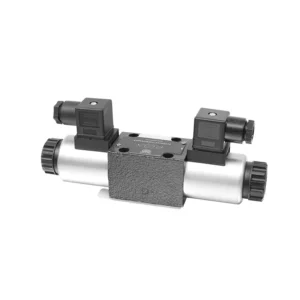

Den direktestyrte proporsjonale retningsventilen for hydraulikk i 4WRA(E)-serien er en toppmoderne hydraulisk komponent som er utviklet for å gi presis kontroll og effektiv drift i hydrauliske systemer. Med sin direktestyrte proporsjonale retningskontrollteknologi tilbyr denne ventilen nøyaktig strømningskontroll, sømløse retningsendringer og optimalisert ytelse.
Den direktestyrte proporsjonale retningsventilen i 4WRA(E)-serien gir hydrauliske systemer presis strømningskontroll, allsidige retningsendringer og optimal energieffektivitet. Den direktestyrte proporsjonale kontrollteknologien sikrer nøyaktig og responsiv drift, mens den høye strømningskapasiteten og den energieffektive designen bidrar til forbedret systemytelse. Ved å følge de anbefalte bruksmetodene og vedlikeholdsretningslinjene kan du maksimere fordelene og levetiden til 4WRA(E)-seriens ventil, og løfte det hydrauliske systemet ditt til nye nivåer av presisjon og effektivitet. Oppgrader det hydrauliske oppsettet ditt i dag og opplev kraften til den direktestyrte proporsjonale retningsventilen i 4WRA(E)-serien.
4WRA(E)-serien direktestyrt proporsjonal retningsbestemt hydraulisk ventil Viktige egenskaper:
- Direktestyrt proporsjonalkontroll:
- 4WRA(E)-seriens ventil benytter direktestyrt proporsjonalkontroll, noe som gir presis og umiddelbar respons på kontrollsignaler.
- Denne funksjonen sikrer nøyaktig flytkontroll og sømløse overganger mellom ulike hydrauliske funksjoner.
- Høy strømningskapasitet:
- Med sin robuste design tilbyr ventilen høy strømningskapasitet, noe som gjør den egnet for applikasjoner som krever betydelig hydraulisk kraft.
- Det muliggjør effektiv håndtering av store væskevolumer, noe som bidrar til forbedret systemytelse.
- Allsidig retningskontroll:
- Ventilen i 4WRA(E)-serien gir allsidig retningskontroll, noe som muliggjør jevne og presise endringer i hydraulikkvæskens retning.
- Det muliggjør sømløs aktivering av hydrauliske komponenter som sylindere, motorer og aktuatorer i forskjellige retninger.
- Energieffektivitet:
- Denne ventilen er designet med tanke på energieffektivitet, minimerer trykkfall og optimaliserer strømningskontrollen, noe som resulterer i redusert energiforbruk.
- Ved å administrere hydraulisk kraft effektivt, bidrar det til å maksimere systemytelsen samtidig som driftskostnadene minimeres.
4WRA(E)-serien direktestyrt proporsjonal retningsbestemt hydraulisk ventil Parameter:
| Hydraulisk | ||||||||
| Installasjonsposisjon | valgfritt, helst horisontalt | |||||||
| Størrelse | 6 | 10 | ||||||
| Vekt | 4WRA…L2X | kg | 2 | 6.6 | ||||
| 4WRAE…L2X | 2.2 | 6.8 | ||||||
| Nominell strømningsmengde qnom, når Δp = 10 bar | l/min | 7, 15, 26 | 30,60 | |||||
| Hysterese | % | ≤5 | ||||||
| Repeterbarhet | % | ≤1 | ||||||
| Responsfølsomhet | % | ≤0,5 | ||||||
| Maks. driftstrykk | Portens ABP | bar | 315 | |||||
| Port T | bar | 210 | ||||||
| Væske | Mineralolje egnet for NBR- og FKM-tetninger | |||||||
| Fosfatester for FKM-tetning | ||||||||
| Væsketemperaturområde | 4WRA…L2X | ℃ | -20 ℃ til 70 ℃ (-4 °F til 158 °F) | |||||
| 4WRAE…L2X | ℃ | -20 ℃ til 50 ℃ (-4° F til 122° F) | ||||||
| Viskositetsområde | mm²/s | 20 til 380 (helst 30 til 46) | ||||||
| Grad av forurensning | NAS1638 klasse 9 eller ISO 4406 klasse 20/18/15 | |||||||
| Elektriske data | ||||||||
| 1) solenoid | ||||||||
| Spenningstype | DC | |||||||
| Kommandoverdisignal | ±10V eller 4~20mA | |||||||
| Maks. strøm per solenoid | EN | 2.5 | 1.5 | 0.8 | ||||
| Spolemotstand | Kald verdi | Ω | 2 | 4.8 | 19.5 | |||
| Maks. varm verdi | 3 | 7.2 | 28.8 | |||||
| Plikt | % | ED100% | ||||||
| Spoletemperatur | ℃ | 150 | ||||||
| Ventilbeskyttelse i henhold til EN 60529 | IP65 | |||||||
| 2) Kontrollelektronikk | ||||||||
| Forsterker | 4WRA…L2X | VT-VSPA2-L2X | ||||||
| 4WRAE…L2X | Integrert i ventilen (OBE) | |||||||
| Driftsspenning | Nominell spenning | VDC | 24 | |||||
| Nedre grenseverdi | V | 21/22 (4WRA), 19 (4WRAE) | ||||||
| Øvre grenseverdi | V | 35 | ||||||
| Forsterkerens strømforbruk | Imax | EN | <1,8 | |||||
| Imax | EN | 3 | ||||||
Fordeler med 4WRA(E)-seriens direktestyrte proporsjonale retningsbestemte hydrauliske ventiler:
• Direktevirkende proporsjonal retningsventil, brukes til å kontrollere strømmen og retningen på væskestrømmen
• Paneltypeinstallasjon
• Proporsjonalsolenoiden aktiverer ventilkjernen gjennom gjengeforbindelsen, og spolen kan fjernes separat
• Justering av spolefjær
• Optional with built-in amplifier, 4WRAE…L2X type input can be A1 or F1
• Støtter tilførsel av ekstern forsterker
Bruksmetode for 4WRA(E)-serien direktestyrt proporsjonal retningsbestemt hydraulisk ventil:
- Systemevaluering:
- Evaluer det hydrauliske systemet ditt og identifiser de spesifikke kravene til flytkontroll og retningsregulering.
- Avgjør om ventilen i 4WRA(E)-serien er egnet basert på dens strømningskapasitet, trykkklassifisering og kompatibilitet med systemet ditt.
- Ventilvalg:
- Velg riktig variant av 4WRA(E)-seriens ventil basert på systemparametrene, strømningskravene og behovene for retningskontroll.
- Vurder faktorer som maksimal strømningshastighet, trykkklassifisering, responstid og driftsforhold.
- Installasjon:
- Follow the manufacturer’s installation instructions carefully, ensuring proper alignment and secure valve mounting.
- Koble ventilen til det hydrauliske systemet. Sørg for lekkasjefrie tilkoblinger og riktig justering av strømningsretningen.
- Kontrollsignaltilkobling:
- Koble styresignalledningene til ventilen til riktig styreenhet, for eksempel en proporsjonalforsterker eller elektronisk styreenhet.
- Sørg for riktig kabling og kompatibilitet mellom ventilen og kontrollenheten for å muliggjøre nøyaktig og responsiv styring.
Hvordan justere ventilklaringen på hydrauliske løftere?
Adjusting valve lash on hydraulic lifters is a crucial maintenance task to ensure proper engine performance and prevent issues such as noisy valves or reduced power. Here’s a step-by-step guide on how to adjust valve lash on hydraulic lifters:
- Preparat:
- Sørg for at motoren er av og avkjølt før du starter justeringsprosessen.
- Familiarize yourself with the engine’s firing order and the specific valve lash specifications provided by the manufacturer for your engine model.
- Identifiser riktig sylinder:
- Locate the firing position of the engine by referring to the engine’s firing order diagram.
- Identifiser sylinderen som tilsvarer den spesifikke ventilen du vil justere.
- Plasser sylinderen:
- Rotate the engine crankshaft manually using a socket wrench or the engine’s built-in turning mechanism.
- Plasser sylinderen du vil justere i øvre dødpunkt (ØDP) på kompresjonsslaget. Du kan gjøre dette ved å justere tidsmerkene på veivakselens remskive eller bruke et stempelstoppverktøy.
- Løsne vippearmen:
- Finn vippearmen på den spesifikke ventilen du vil justere.
- Løsne vippearmsmutteren eller justeringsskruen med en passende skiftenøkkel eller pipenøkkel.
- Juster ventilklaringen:
- Med vippearmen løs kan du nå justere ventilklaringen. Ventilklaringen er klaringen mellom vippearmen og ventilstammen.
- Bruk en følermåler til å måle den eksisterende ventilklaringen. Sett inn riktig tykkelsesmåler mellom vippearmen og ventilstammen.
- Hvis klaringen er for stram, noe som betyr at følerbladet ikke passer eller har for stor motstand, må du øke ventilklaringen. Hvis klaringen er for løs, noe som betyr at følerbladet glir inn for lett, må du redusere ventilklaringen.
- To adjust the valve lash, tighten or loosen the rocker arm nut or adjuster screw accordingly. Refer to the manufacturer’s specifications for the recommended amount of adjustment to be made.
- Sjekk ventilklaringen på nytt:
- Etter at du har gjort justeringen, sjekk ventilklaringen på nytt med søkerbladet for å sikre at den er innenfor de anbefalte spesifikasjonene.
- Gjenta justeringsprosessen om nødvendig til riktig ventilklaring er oppnådd.
- Gjenta for andre sylindere:
- Gå videre til neste sylinder i tenningsrekkefølgen og gjenta trinn 4 til 6 for hver sylinder du vil justere.
- Husk å rotere veivakselen og plassere hver sylinder i ØDP på kompresjonsslaget før du justerer ventilklaringen.
- Fest vippearmen:
- Once the valve lash is properly adjusted for each cylinder, tighten the rocker arm nut or adjuster screw to the manufacturer’s recommended torque specification.
- Dobbeltsjekk at ventilklaringen forblir innenfor det angitte området etter tilstramming.
- Sluttkontroller:
- Roter motorens veivaksel et par ganger for å sikre jevn rotasjon, og sjekk for uvanlige lyder eller motstand.
- Start motoren og lytt etter unormale ventilstøy. Hvis du hører overdreven banking eller tapping, kontroller ventilklaringen på nytt.
Fabrikkens kapasitet og kapasitet:
(1) Montering
Vi har en førsteklasses uavhengig forsknings- og utviklingsplattform for montering. Verkstedet for produksjon av hydrauliske sylindere har fire halvautomatiske monteringslinjer for løftesylindere og én automatisk monteringslinje for vippesylindere, med en årlig produksjonskapasitet på 1 million enheter. Spesialsylinderverkstedet er utstyrt med ulike spesifikasjoner for et halvautomatisk rengjøringsmonteringssystem med en årlig produksjonskapasitet på 200 000 enheter, og er utstyrt med kjent CNC-maskineringsutstyr, et maskineringssenter, spesialutstyr for høypresisjons sylinderbehandling, en robotsveisemaskin, en automatisk rengjøringsmaskin, en automatisk sylindermonteringsmaskin og en automatisk produksjonslinje for lakkering. Vi har mer enn 300 sett (sett) av kritisk utstyr. Optimal allokering og effektiv bruk av utstyrsressurser sikrer nøyaktighetskravene til produktene og oppfyller produktenes høye kvalitetsbehov.


(2) Maskinering
Maskineringsverkstedet er utstyrt med et spesialtilpasset dreiesenter for skrå skinner, maskineringssenter, høyhastighets honemaskin, sveiserobot og annet relatert utstyr, som kan håndtere bearbeiding av sylinderrør med en maksimal indre diameter på 400 mm og en maksimal lengde på 6 meter.


(3) Sveising


(4) Maling og belegg
Med små og mellomstore sylinderautomatiske vannbaserte malingsbeleggslinjer, for å oppnå automatisk robotlasting og -lossing og automatisk sprøyting, er den designede kapasiteten 4000 stykker per skift;
Vi har også en halvautomatisk produksjonslinje for maling for store sylindere drevet av en kabelkjede, med en designkapasitet på 60 kasser per skift.


(5) Testing
Vi har førsteklasses inspeksjonsfasiliteter og testbenker for å sikre at sylinderens ytelse oppfyller kravene.


Vi er en av de beste produsentene av hydrauliske sylindere. Vi kan tilby et omfattende utvalg av hydrauliske sylindere. Vi tilbyr også tilsvarende landbruksgirkasserVi har eksportert produktene våre til kunder over hele verden og opparbeidet oss et godt rykte på grunn av vår overlegne produktkvalitet og ettersalgsservice. Vi ønsker kunder i inn- og utland velkommen til å kontakte oss for å forhandle om forretninger, utveksle informasjon og samarbeide med oss!