

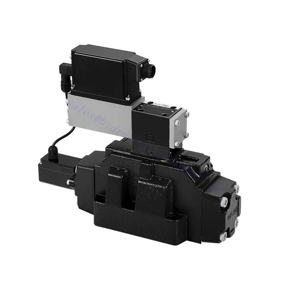
4WRLE Series Pilot Operated Proportional Directional Hydraulic Valve
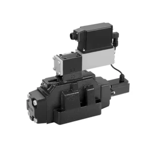

The 4WRLE series pilot-operated proportional directional hydraulic valve is a cutting-edge hydraulic component that revolutionizes fluid control in hydraulic systems. This valve combines pilot-operated technology with proportional directional control, offering precise flow regulation and exceptional efficiency.
The 4WRLE series pilot-operated proportional directional hydraulic valve elevates hydraulic control to new heights of precision and efficiency. With its pilot-operated technology and proportional directional control, this valve ensures accurate flow regulation, optimized energy consumption, and enhanced system performance. By following the recommended usage methods and maintenance guidelines, you can unleash the full potential of the 4WRLE series valve and achieve superior hydraulic control. Upgrade your hydraulic system today and experience the power of precision with the 4WRLE series pilot-operated proportional directional hydraulic valve.
4WRLE Series Pilot Operated Proportional Directional Hydraulic Valve Key Characteristics:
- Pilot Operated Technology:
- The 4WRLE series valve incorporates pilot-operated technology, allowing precise fluid flow control and pressure regulation.
- This technology enables efficient energy usage and reduces heat generation, resulting in improved overall system performance and reduced operating costs.
- Proporsjonal retningskontroll:
- With its proportional directional control capability, this valve provides accurate and balanced flow adjustment based on control signals.
- The proportional control allows for smooth and precise control of hydraulic actuators, enhancing system performance and minimizing wear and tear.
- Allsidig funksjonalitet:
- The 4WRLE series valve offers versatile control over fluid direction, making it suitable for a wide range of hydraulic applications.
- Whether it’s controlling cylinders, motors, or other hydraulic components, this valve ensures seamless activation and deactivation in different directions, enhancing system flexibility and adaptability.
- Høy strømningskapasitet:
- Designed to handle high flow rates, the 4WRLE series valve delivers exceptional performance even in demanding applications.
- Its robust construction and optimized flow channels ensure reliable operation and consistent flow control, meeting the requirements of high-power hydraulic systems.
4WRLE Series Pilot Operated Proportional Directional Hydraulic Valve Parameter:
NG6
| General | |||||||
| Design | Spoleventil, direktestyrt, med stålhylse | ||||||
| Aktivering | Proporsjonal solenoid med posisjonskontroll, OBE | ||||||
| Tilkoblingstype | Montering av underplate, portmønster i henhold til ISO 4401-03-02-0-05 | ||||||
| Installasjonsposisjon | Noen | ||||||
| Omgivelsestemperaturområde | ℃ | -20…+50 | |||||
| Vekt | kg | omtrent 2,75 | |||||
| Maksimal vibrasjonsmotstand (testtilstand) | Maks. 25 g, vibrasjonstest i alle retninger i rommet (24 timer) | ||||||
| Hydraulisk (målt ved p=100 bar, med HLP46 ved ϑolje = 40℃ ±5℃) | |||||||
| Trykkvæske | Mineralolje (HL, HLP) i henhold til DIN 51 524 | ||||||
| Viskositetsområde | anbefalt | mm²/s | 20…100 | ||||
| maks. tillatt | mm²/s | 10…800 | |||||
| Trykkvæsketemperaturområde | ℃ | -20 til +70 | |||||
| Maksimal tillatt forurensningsgrad av trykkvæske Renhetsklasse i henhold til ISO 4406 (c) | Klasse 18/16/13 | ||||||
| Nominell strømning (Δp = 35 bar per kant) | l/min | 2 | 4 | 12 | 24 | 40 | |
| Maks. driftstrykk | bar | Port A, B, P: 315 | |||||
| Maks. trykk | bar | Port T: 250 | |||||
| Lekkasjestrøm ved 100 bar | Lineær | cm³/min | <150 | <180 | <300 | <500 | <900; |
| Ikke-lineær | cm³/min | / | / | / | <300 | <450; | |
| Statisk/Dynamisk | |||||||
| Hysterese | % | ≤0,2 | |||||
| Actuating time for signal step 0 … 100% | ms | 10 | |||||
| Temperaturdrift | Nullforskyvning < 1% ved ΔT = 40 ℃ | ||||||
| Null kompensasjon | Fra fabrikk ±1% | ||||||
| Elektrisk kontrollelektronikk integrert i ventilen | |||||||
| Relativ driftssyklus | % | 100ED | |||||
| Grad av beskyttelse | IP65 | ||||||
| Forbindelse | Pluggkontakt 6P+PE, DIN 43563 | ||||||
| Forsyningsspenning Terminal A Terminal B |
24VDCnavn | ||||||
| min. 21 VDC / maks. 40 VDC | |||||||
| 0V (ripple maks. 2) | |||||||
| Sikring, ekstern | AF | 2.5 | |||||
| nput, version “A1” Terminal D (UE) Terminal E |
Differensialforsterker, Ri = 100 kΩ | ||||||
| 0…±10V | |||||||
| 0V | |||||||
| Input, version “F1” Terminal D (ID-E) Terminal E (ID-E) |
Last, Rsh = 200 Ω | ||||||
| 4…12…20mA | |||||||
| Strømsløyfe IDE retur | |||||||
| Test signal, version “A1” Terminal F (UTest) Terminal C |
LVDT | ||||||
| 0…±10V | |||||||
| Referanse 0 V | |||||||
| Test signal, version “F1” Terminal F (I FC ) Terminal C (I) FC ) |
LVDT signal 4 … (12) … 20 mA on external load 200 … 500 Ωmaximum | ||||||
| 4 … (12) … 20mA (output) | |||||||
| Strømsløyfe IFC retur | |||||||
| Innstilling | Kalibrert før levering, se karakteristikkurver | ||||||
NG10
| General | |||||
| Design | Spoleventil, direkte betjent, med stålhylse | ||||
| Aktivering | Proporsjonal solenoid med posisjonskontroll, OBE | ||||
| Tilkoblingstype | Plateport, portmønster (ISO 4401-05-04-0-05) | ||||
| Installasjonsposisjon | Noen | ||||
| Omstendigheter temperaturområde | ℃ | -20…+50 | |||
| Vekt | kg | omtrent 7,1 | |||
| Maksimal vibrasjonsmotstand (testtilstand) | Maks. 25 g, vibrasjonstest i alle retninger i rommet (24 timer) | ||||
| Hydraulisk (målt med HLP 46, ϑolje = 40℃ ±5℃) | |||||
| Trykkvæske | Hydraulic oil according to DIN 51524…535 | ||||
| Viskositetsområde | anbefalt | mm²/s | 20…100 | ||
| Maks. tillatt | mm²/s | 10…800 | |||
| Trykkvæsketemperaturområde | ℃ | -20 til +70 | |||
| Maks. tillatt grad av forurensning av hydraulikkvæsken, renhetsklasse i henhold til ISO 4406 (c) | Klasse 18/16/13 | ||||
| Nominell strømning (Δp = 35 bar per kant) | l/min | 50 | 100 | ||
| Maks. driftstrykk | bar | Port PAB: 315 | |||
| Maks. trykk | bar | Port T: 250 | |||
| Lekkasjestrøm ved 100 bar | Lineær | cm³/min | <1200 | <1500 | |
| Ikke-lineær | cm³/min | <600 | <600 | ||
| Statisk/Dynamisk | |||||
| Hysterese | % | ≤0,2 | |||
| Actuating time for signal step 0 … 100% | ms | 25 | |||
| Temperaturdrift | Nullforskyvning < 1% ved ΔT = 40 ℃ | ||||
| Null kompensasjon | Fra fabrikk ±1% | ||||
| Elektrisk kontrollelektronikk integrert i ventilen | |||||
| Relativ driftssyklus | % | 100ED | |||
| Grad av beskyttelse | IP65 (med paringskontakt montert og låst) | ||||
| Forbindelse | Sammenkobling 6P+PE, DIN 43563 | ||||
| Forsyningsspenning Terminal A Terminal B |
24VDCnavn | ||||
| min. 21 VDC / maks. 40 VDC | |||||
| Rippel maks. 2 VDC | |||||
| Sikring, ekstern | AF | 2.5 | |||
| Input, version “A1” Terminal D (UE) Terminal E |
Differensialforsterker, Ri = 100 kΩ | ||||
| 0…±10V | |||||
| 0V | |||||
| Input, version “F1” Terminal D (IDE) Terminal E (IDE) |
Last, Rsh = 200 | ||||
| 4…12…20mA | |||||
| Strømsløyfe IDE retur | |||||
| Test signal, version “A1” Terminal F (UTest) Terminal C |
LVDT | ||||
| 0…±10V | |||||
| Referanse 0 V | |||||
| Test signal, version “F1” Terminal F (I FC ) Terminal C (I) FC ) |
LVDT | ||||
| 4…20 mA output | |||||
| Strømsløyfe IFC tilbakemelding | |||||
4WRLE Series Pilot Operated Proportional Directional Hydraulic Valve Advantages:
• Direktevirkende servo-magnetventil med kontrollstempel og ventilhylse, med servoytelse
• Single-side drive, optional, with power-off safety function
Kontrollmagnet med innebygd tilbakemelding og integrert forsterkerkort (OBE), fabrikkinnstilt
• Electrical connection 6P+PE signal input differential amplifier with interface, input optional A1: ±10V, or interface F1: 4…20mA (Rsh =200Ω)
• Panel mounting: the mounting surface complies with ISO 4401-03-02
Usage Method Of 4WRLE Series Pilot Operated Proportional Directional Hydraulic Valve:
- Systemvurdering:
- Evaluate your hydraulic system and define the specific flow and directional control requirements.
- Identify whether the 4WRLE series valve is compatible with your system based on factors such as flow capacity, pressure rating, and compatibility with your application.
- Ventilvalg:
- Select the appropriate variant of the 4WRLE series valve based on your system parameters, flow requirements, and directional control needs.
- Consider factors such as maximum flow rate, pressure rating, response time, and environmental operating conditions.
- Installasjon:
- Follow the manufacturer’s installation instructions carefully to ensure proper alignment and secure valve mounting.
- Create leak-free connections and ensure correct flow direction alignment to guarantee optimal performance.
- Integrering av kontrollsignaler:
- Koble styresignalledningene til ventilen til en passende styreenhet, for eksempel en proporsjonalforsterker eller elektronisk styreenhet.
- Ensure proper wiring and compatibility between the valve and control device to achieve accurate and responsive control.
How To Hook Up A Hydraulic Flow Control Valve?
To hook up a hydraulic flow control valve, follow these steps:
- Identify Valve Type: Determine the specific type of flow control valve you are working with. Common types include needle valves, adjustable flow control valves, or pressure-compensated flow control valves. Ensure that the valve is suitable for your application and compatible with your hydraulic system.
- Gather Required Tools and Materials: Collect the necessary tools and materials, including appropriate hydraulic fittings, adapters, hoses, and wrenches.
- Klargjør det hydrauliske systemet: Shut down the hydraulic system and relieve any pressure in the system by activating the relief valve or retracting any hydraulic cylinders. This step is crucial for safety.
- Identify Flow Direction: Identify the flow direction in your hydraulic system. Typically, the flow direction is indicated by arrows on the hydraulic components. Ensure that you understand the correct flow direction before proceeding.
- Locate Installation Point: Determine the optimal location to install the flow control valve in your hydraulic system. Consider factors such as accessibility, proximity to the actuator or hydraulic component, and ease of adjustment.
- Monter ventilen: Securely mount the flow control valve in the chosen location using appropriate brackets or clamps. Ensure the valve is positioned correctly, aligning the inlet and outlet ports with the flow direction.
- Koble til innløps- og utløpsportene: Attach hydraulic hoses or tubing to the inlet and outlet ports of the flow control valve. Use suitable hydraulic fittings and adapters to create a leak-free connection. Tighten the connections using wrenches to ensure a secure fit, but avoid over-tightening.
- Adjust the Flow Control: Depending on the type of flow control valve, it may have adjustable features such as a needle valve or a flow control knob. Adjust the valve according to your desired flow rate or speed. Refer to the manufacturer’s instructions for specific adjustment procedures.
- Test systemet: Once the flow control valve is installed and adjusted, slowly restore hydraulic system pressure. Test the system to ensure that the flow control valve is functioning correctly. Monitor the flow rate or speed of the hydraulic actuator to verify that it is within the desired range.
- Fine-tune and Monitor: Adjust the flow control valve to achieve the desired flow rate or speed. Regularly monitor the hydraulic system for leaks, pressure inconsistencies, or unusual behavior.
Fabrikkens kapasitet og kapasitet:
(1) Montering
Vi har en førsteklasses uavhengig forsknings- og utviklingsplattform for montering. Verkstedet for produksjon av hydrauliske sylindere har fire halvautomatiske monteringslinjer for løftesylindere og én automatisk monteringslinje for vippesylindere, med en årlig produksjonskapasitet på 1 million enheter. Spesialsylinderverkstedet er utstyrt med ulike spesifikasjoner for et halvautomatisk rengjøringsmonteringssystem med en årlig produksjonskapasitet på 200 000 enheter, og er utstyrt med kjent CNC-maskineringsutstyr, et maskineringssenter, spesialutstyr for høypresisjons sylinderbehandling, en robotsveisemaskin, en automatisk rengjøringsmaskin, en automatisk sylindermonteringsmaskin og en automatisk produksjonslinje for lakkering. Vi har mer enn 300 sett (sett) av kritisk utstyr. Optimal allokering og effektiv bruk av utstyrsressurser sikrer nøyaktighetskravene til produktene og oppfyller produktenes høye kvalitetsbehov.


(2) Maskinering
Maskineringsverkstedet er utstyrt med et spesialtilpasset dreiesenter for skrå skinner, maskineringssenter, høyhastighets honemaskin, sveiserobot og annet relatert utstyr, som kan håndtere bearbeiding av sylinderrør med en maksimal indre diameter på 400 mm og en maksimal lengde på 6 meter.


(3) Sveising


(4) Maling og belegg
Med små og mellomstore sylinderautomatiske vannbaserte malingsbeleggslinjer, for å oppnå automatisk robotlasting og -lossing og automatisk sprøyting, er den designede kapasiteten 4000 stykker per skift;
Vi har også en halvautomatisk produksjonslinje for maling for store sylindere drevet av en kabelkjede, med en designkapasitet på 60 kasser per skift.


(5) Testing
Vi har førsteklasses inspeksjonsfasiliteter og testbenker for å sikre at sylinderens ytelse oppfyller kravene.


Vi er en av de beste produsentene av hydrauliske sylindere. Vi kan tilby et omfattende utvalg av hydrauliske sylindere. Vi tilbyr også tilsvarende landbruksgirkasserVi har eksportert produktene våre til kunder over hele verden og opparbeidet oss et godt rykte på grunn av vår overlegne produktkvalitet og ettersalgsservice. Vi ønsker kunder i inn- og utland velkommen til å kontakte oss for å forhandle om forretninger, utveksle informasjon og samarbeide med oss!