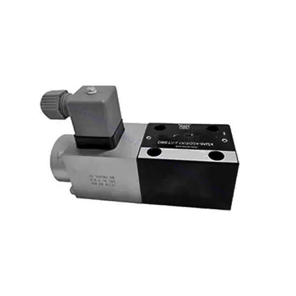
DBETX Series Proportional Pressure Relief Hydraulic Valve
DBETX Series Proportional Pressure Relief Hydraulic Valve
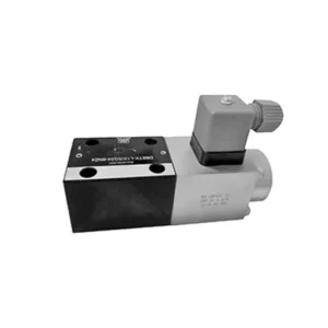
The DBETX series proportional pressure relief hydraulic valve is a versatile and high-performance hydraulic component designed to provide precise pressure relief in hydraulic systems. Engineered with advanced proportional control technology, this valve ensures optimal performance, efficiency, and safety.
The DBETX series proportional pressure relief hydraulic valve empowers hydraulic systems with precise pressure control, enhanced efficiency, and equipment protection. With its proportional pressure relief capabilities, this valve ensures optimal performance across a wide range of applications. By following the recommended usage methods and maintenance guidelines, you can maximize the benefits and reliability of the DBETX series valve, elevating the performance and control of your hydraulic system. Upgrade your hydraulic setup today and experience superior pressure regulation with the DBETX series proportional pressure relief hydraulic valve.
DBETX Series Proportional Pressure Relief Hydraulic Valve Key Characteristics:
- Proportional Pressure Relief:
- The DBETX series valve delivers proportional pressure relief, allowing for accurate and dynamic hydraulic pressure control.
- It ensures precise pressure regulation in response to varying load conditions, preventing damage to hydraulic components and optimizing system performance.
- Forbedret systemeffektivitet:
- This valve enables precise control of hydraulic flow rates, resulting in enhanced system efficiency and reduced energy consumption.
- Maintaining the desired pressure levels minimizes pressure fluctuations, enhances overall productivity, and reduces operational costs.
- Safety and Equipment Protection:
- The DBETX series valve acts as a safeguard by limiting the pressure within the hydraulic system, protecting equipment and operators from potential damage or accidents.
- It prevents overloading and ensures the longevity of hydraulic components, reducing the risk of system failures and downtime.
- Bredt spekter av bruksområder:
- With its versatile design and compatibility with various hydraulic systems, the DBETX series valve can be used in a wide range of applications across industries such as manufacturing, construction, agriculture, and more.
- It offers flexibility and adaptability, making it suitable for diverse hydraulic setups and requirements.
DBETX Series Proportional Pressure Relief Hydraulic Valve Parameter:
| General | ||||||
| Konstruksjon | Poppet valve, direct drive | |||||
| Aktivering | Proportional solenoid without position control, external amplifier | |||||
| Tilkoblingstype | Subplate, mounting hole configuration NG6 (ISO 4401-03-02-0-94) | |||||
| Installasjonsposisjon | Valgfri | |||||
| Omstendigheter temperaturområde | ℃ | -20…+50 | ||||
| Vekt | kg | about 2.1 | ||||
| Vibration resistance, test condition | Max. 25 g, shaken in 3 dimensions(24 h) | |||||
| Hydraulic (measured with HLP 46, Voil=40℃±5℃) | ||||||
| Trykkvæske | Hydraulic oil to DIN 51524…535, other fluids after prior consultation | |||||
| Viskositetsområde | anbefalt | 20…100 | ||||
| maks. tillatt | 10…800 | |||||
| Trykkvæsketemperaturområde | ℃ | -20…+80 | ||||
| Maximum permitted degree of contamination of pressure fluid Purity class to ISO 4406(c) | Klasse 18/16/13 | |||||
| Direction of flow | See symbol | |||||
| Max. setting pressure (Q = 1 l/min) | bar | 50 | 80 | 180 | 250 | 315 |
| Min. settable pressure (Q = 1 l/min) | bar | 2 | 3 | 4 | 5 | 8 |
| Max. operating pressure(Q = 1 l/min) | bar | Port P: 315 | ||||
| Maks. trykk | bar | Port T: 250 | ||||
| Max. mechanical pressure limitation level, e.g. when solenoid current I>Imax | bar | <55 | <85 | <186 | <258 | <325 |
| Statisk/Dynamisk | ||||||
| Hysterese | % | ≤4 | ||||
| Response time 100% signal changen | ms | On<60 / Off<70 | ||||
| Range of inversion | % | ≤3 | ||||
| Elektriske data | ||||||
| Cyclic duration factor | % | 100 ED | ||||
| Grad av beskyttelse | IP 65 to DIN 40050 and IEC 14434/5 | |||||
| Solenoid connection | Plug-in connector to DIN EN 175301-803/ISO 4400 | |||||
| Power | 24VDCnom | |||||
DBETX Series Proportional Pressure Relief Hydraulic Valve Advantages:
• Direkte, for å begrense systemtrykket
• Can adjust pressure by controlling the current with the solenoid according to the characteristic curve
• In the event of electrical failure, the restricted pressure is still within safety level (solenoid current > Imax)
• External amplifying sub-plate mounting has slope and valve calibration functions (separate order)
Usage Method Of DBETX Series Proportional Pressure Relief Hydraulic Valve:
- Systemevaluering:
- Evaluate your hydraulic system and identify the specific requirements for pressure control and relief.
- Determine if the DBETX series valve is compatible with your system and suitable for your application based on its pressure range, flow capacity, and other specifications.
- Ventilvalg:
- Choose the appropriate DBETX series valve variant based on your system parameters, pressure range, and flow requirements.
- Consider maximum pressure rating, response time, and operational conditions.
- Installasjon:
- Følg produsentens installasjonsinstruksjoner nøye, og sørg for riktig justering og sikker montering av ventilen.
- Koble ventilen til det hydrauliske systemet. Sørg for lekkasjefrie tilkoblinger og riktig justering av strømningsretningen.
- Trykkjustering:
- Adjust the pressure relief setting on the DBETX series valve to match the desired pressure range for your application.
- Utilize the proportional control signals or adjustment mechanisms provided with the valve to achieve precise pressure regulation.
How To Adjust A Hydraulic Pressure Relief Valve?
Adjusting a hydraulic pressure relief valve allows you to set the desired maximum pressure in a hydraulic system. This is important for maintaining system integrity and preventing damage to components. Here’s a step-by-step guide on how to adjust a hydraulic pressure relief valve:
- Identify the Pressure Relief Valve:
- Locate the pressure relief valve in your hydraulic system. It is typically installed in the hydraulic line and often near the pump or control valve.
- Understand the Valve Design:
- Familiarize yourself with the specific design of the pressure relief valve you are working with. Different valves may have varying adjustment mechanisms, such as a knob, screw, or locknut.
- Determine the Desired Pressure:
- Assess the requirements of your hydraulic system and determine the desired maximum pressure. This will guide you in adjusting the pressure relief valve accurately.
- Klargjør systemet:
- Before making any adjustments, shut off the hydraulic system and relieve the pressure by moving the control levers back and forth or following the manufacturer’s recommended procedure.
- Locate the Adjustment Mechanism:
- Identify the adjustment mechanism on the pressure relief valve. It could be a knob, screw, or locknut positioned on the valve body or adjacent to it.
- Adjust the Valve:
- If the valve has a knob or handle, turn it clockwise to increase the pressure relief setting or counterclockwise to decrease it. If the valve has a screw, turn it clockwise to increase the pressure relief or counterclockwise to decrease it.
- Make Incremental Adjustments:
- When adjusting the pressure relief valve, make small, incremental changes to avoid sudden or drastic variations in pressure. This allows you to fine-tune the maximum pressure and achieve the desired performance.
- Observe the System:
- With each adjustment, observe the hydraulic system and its components. Pay attention to the pressure gauge readings to see if they align with the desired maximum pressure.
- Test og verifiser:
- Operate the hydraulic system and monitor the pressure to ensure that it remains within the desired range. Check for any pressure fluctuations or irregularities that may indicate the need for further adjustment.
- Lock the Adjustment:
- Once you have achieved the desired pressure relief setting, secure the adjustment mechanism to prevent unintended changes. Some valves may have a locking nut or set screw that can be tightened to hold the adjustment in place.
- Monitor and Revisit:
- Regularly monitor the pressure relief valve and the hydraulic system. If there are changes in the system or if the desired maximum pressure needs to be adjusted, revisit the pressure relief valve and repeat the adjustment process as needed.
Fabrikkens kapasitet og kapasitet:
(1) Montering
Vi har en førsteklasses uavhengig forsknings- og utviklingsplattform for montering. Verkstedet for produksjon av hydrauliske sylindere har fire halvautomatiske monteringslinjer for løftesylindere og én automatisk monteringslinje for vippesylindere, med en årlig produksjonskapasitet på 1 million enheter. Spesialsylinderverkstedet er utstyrt med ulike spesifikasjoner for et halvautomatisk rengjøringsmonteringssystem med en årlig produksjonskapasitet på 200 000 enheter, og er utstyrt med kjent CNC-maskineringsutstyr, et maskineringssenter, spesialutstyr for høypresisjons sylinderbehandling, en robotsveisemaskin, en automatisk rengjøringsmaskin, en automatisk sylindermonteringsmaskin og en automatisk produksjonslinje for lakkering. Vi har mer enn 300 sett (sett) av kritisk utstyr. Optimal allokering og effektiv bruk av utstyrsressurser sikrer nøyaktighetskravene til produktene og oppfyller produktenes høye kvalitetsbehov.


(2) Maskinering
Maskineringsverkstedet er utstyrt med et spesialtilpasset dreiesenter for skrå skinner, maskineringssenter, høyhastighets honemaskin, sveiserobot og annet relatert utstyr, som kan håndtere bearbeiding av sylinderrør med en maksimal indre diameter på 400 mm og en maksimal lengde på 6 meter.

(3) Sveising

(4) Maling og belegg
Med små og mellomstore sylinderautomatiske vannbaserte malingsbeleggslinjer, for å oppnå automatisk robotlasting og -lossing og automatisk sprøyting, er den designede kapasiteten 4000 stykker per skift;
Vi har også en halvautomatisk produksjonslinje for maling for store sylindere drevet av en kabelkjede, med en designkapasitet på 60 kasser per skift.


(5) Testing
Vi har førsteklasses inspeksjonsfasiliteter og testbenker for å sikre at sylinderens ytelse oppfyller kravene.

Vi er en av de beste produsentene av hydrauliske sylindere. Vi kan tilby et omfattende utvalg av hydrauliske sylindere. Vi tilbyr også tilsvarende landbruksgirkasserVi har eksportert produktene våre til kunder over hele verden og opparbeidet oss et godt rykte på grunn av vår overlegne produktkvalitet og ettersalgsservice. Vi ønsker kunder i inn- og utland velkommen til å kontakte oss for å forhandle om forretninger, utveksle informasjon og samarbeide med oss!