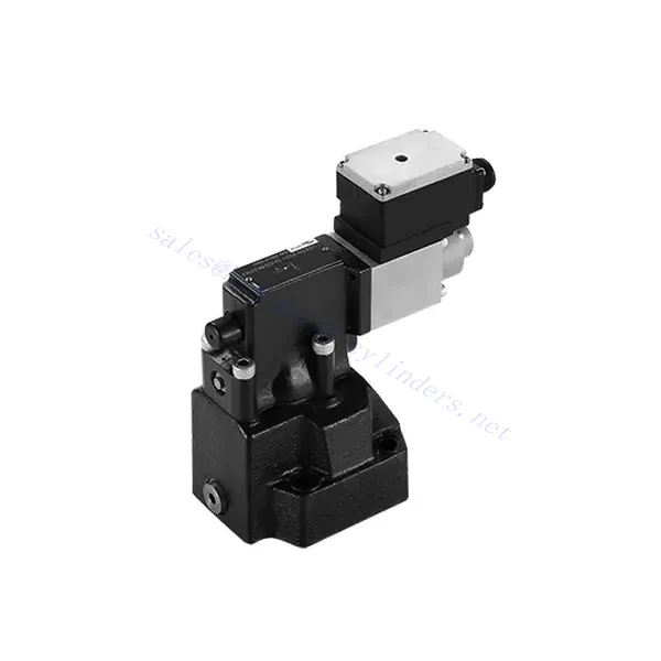
DRE(E) Series Proportional Pressure Reducing Valve
Som en av produsentene, leverandørene og eksportørene av mekaniske produkter tilbyr vi hydrauliske sylindere og mange andre produkter.
Ta kontakt med oss for mer informasjon.
Post:sales@hydraulic-cylinders.net
Produsent, leverandør og eksportør av hydrauliske sylindere.
DRE(E) Series Proportional Pressure Reducing Valve
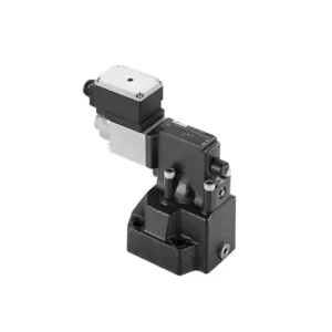
The DRE(E) series proportional pressure reducing valve is a state-of-the-art hydraulic component that delivers precise and reliable pressure control in various industrial applications. With its advanced features, exceptional performance, and robust construction, this valve offers a solution that optimizes system efficiency and enhances productivity.
The DRE(E) series proportional pressure reducing valve offers precise and reliable pressure control for hydraulic systems. With exceptional proportional control, pressure reduction function, high flow capacity, and fast response time, this valve provides accurate pressure regulation and safeguards downstream components. By following the recommended usage methods and maintenance guidelines, you can harness the full potential of this valve and achieve enhanced performance in your hydraulic applications. Upgrade your hydraulic system today with the DRE(E) series proportional pressure reducing valve and experience optimal pressure control with precision and reliability.
DRE(E) Series Proportional Pressure Reducing Valve Key Characteristics:
- Proporsjonal kontroll:
- The DRE(E) series valve boasts exceptional proportional control capabilities, enabling precise adjustment of pressure levels.
- This advanced control feature ensures accurate pressure regulation tailored to specific system requirements, promoting efficient and optimized performance.
- Pressure Reduction Function:
- Equipped with a pressure reduction function, this valve efficiently lowers the incoming pressure to a predefined setpoint.
- By accurately reducing the pressure, the valve protects downstream components, preventing damage and ensuring stable system operation.
- Høy strømningskapasitet:
- The DRE(E) series valve is designed to handle high flow rates, making it suitable for applications that require substantial fluid volumes.
- Den høye strømningskapasiteten muliggjør effektiv drift selv i krevende industrielle miljøer.
- Rask responstid:
- With an impressive response time, this valve allows for rapid adjustments to pressure changes within the system.
- The fast response ensures precise control, minimizing pressure fluctuations and promoting stable and consistent system performance.
DRE(E) Series Proportional Pressure Reducing Valve Parameter:
| General | |||||
| Væske | Mineralolje egnet for NBR- og FKM-tetninger | ||||
| Fosfatester for FKM-tetning | |||||
| Væsketemperaturområde | ℃ | -30 til +80 (NBR-tetning) | |||
| -20 til +80 (FKM-tetning) | |||||
| Viskositetsområde | mm2/s | 2,8 til 380 | |||
| Grad av forurensning | Maksimal tillatt grad av væskeforurensning: Klasse 9. NAS 1638 eller 20/18/15, ISO4406 | ||||
| Maks. driftstrykk | Port A,B | bar | 315 | ||
| Port Y | Separat og med nulltrykk til tanken | ||||
| Maks. innstillingstrykk | Havn A | bar | 50; 100; 200; 315 | ||
| Min. innstillbart trykk | Havn A | In relation to Flow (Q), see characteristic curves | |||
| Pressure at current value 0 in port A | =Min. settable pressure (Refer to the characteristic curve ) | ||||
| Max. pressure safety (infinitely adjustable) | Innstilling av trykk | Pressure range under Max. safety pressure | |||
| 50 bar | 10-60+20 bar | ||||
| 100 bar | 10-120+20 bar | ||||
| 200 bar | 10-220+20 bar | ||||
| 315 bar | 10-340+20 bar | ||||
| Max. pressure safety setting condition | When rated pressure=50 bar, between 60~80 bar | ||||
| When rated pressure=100 bar, between 120~140 bar | |||||
| When rated pressure=200 bar, between 220~240 bar | |||||
| When rated pressure=315 bar, between 340~360 bar | |||||
| Størrelse | 10 | 25 | 32 | ||
| Maks. strømningshastighet | l/min | 80 | 200 | 300 | |
| Pilot flow-rate (for pilot valve) | l/min | 0.7 to 2 | |||
| Linearitet | ±3.5% | ||||
| Repeterbarhet | <±2% | ||||
| Hysterese | with shimmy | without shimmy | |||
| ±2.5% Pmax( 200Hz, amplitude 200mAsss) | ±4.5% Pmax | ||||
| Byttetid | 100 to 300ms (undependent with the system) | ||||
| Elektriske data | |||||
| Power | DC | ||||
| Min. solenoid current | mA | 100 | |||
| Max. solenoid current | mA | 800 | |||
| Spolemotstand | 19.5Ω at 20℃, Max. warm value :28.8Ω | ||||
| Working status | Continuous | ||||
| Max. ambient temperature range | +50℃ | ||||
| Elektrisk tilkobling | Plug-in connector to DIN 43650/2+SL/PG11 | ||||
| Insulation to DIN 40 050 | IP65 | ||||
| Forsterker | VT2000 | ||||
DRE(E) Series Proportional Pressure Reducing Valve Advantages:
• Brukes for montering av bunnplate
• Installation face follow DIN 24340 D and ISO 5781
• Brukes i installasjon av oljebaneblokk
• Fire trykkområder
• Highest pressure protection structure (optional)
• Matching electronic amplifier VT-2000 type (must be ordered separately)
Usage Method Of DRE(E) Series Proportional Pressure Reducing Valve :
- Systemevaluering:
- Evaluate your hydraulic system’s requirements, considering flow rate, pressure range, and system dynamics.
- Determine whether the proportional pressure control offered by the DRE(E) series valve aligns with your system’s needs.
- Ventilvalg:
- Select the appropriate variant of the DRE(E) series valve based on your system parameters and performance requirements.
- Consider factors like flow capacity, pressure range, and compatibility with other system components to ensure optimal functionality.
- Installasjon:
- Follow the manufacturer’s installation instructions carefully to ensure proper placement and secure valve mounting.
- Plasser ventilen riktig i det hydrauliske systemet, med tanke på faktorer som væskens strømningsretning og tilgjengelighet for vedlikehold.
- Pressure Setting:
- Set the desired pressure level by adjusting the valve’s control mechanism according to the manufacturer’s guidelines.
- Ensure that the setpoint aligns with the specific requirements of your system.
How To Remove A Shower Valve Cartridge?
Removing a shower valve cartridge may vary depending on the specific model and manufacturer. However, here is a general step-by-step guide that can help you remove a shower valve cartridge:
- Turn off the Water Supply: Locate the main water shut-off valve for your shower and turn it off to cut off the water supply. This step is essential to prevent any water flow while you work on removing the cartridge.
- Remove the Shower Handle: Most shower handles have a screw or decorative cap at the base. Look for this screw or cap and remove it using a screwdriver or by gently prying it off. Once removed, take off the handle by pulling it straight out.
- Access the Cartridge: Depending on the type of shower valve you have, you may need to remove additional parts to access the cartridge. This can include a trim plate or escutcheon that covers the valve. Use a screwdriver to remove any screws holding these parts in place and gently pull them away.
- Remove the Retaining Clip or Nut: Look for a retaining clip or nut that holds the cartridge in place. This clip or nut is usually located on the top of the cartridge and secures it to the valve body. Use pliers or an adjustable wrench to loosen and remove the clip or nut.
- Remove the Cartridge: Once the retaining clip or nut is removed, you can proceed to pull out the cartridge. Grip the cartridge firmly and pull it straight out of the valve body. If it is stuck, you may need to wiggle it gently or use a cartridge removal tool specific to your shower valve model.
- Rengjør og inspiser: With the cartridge removed, take a moment to clean any debris or sediment from the valve body using a soft brush or cloth. Inspect the cartridge for any signs of damage or wear. If necessary, replace the cartridge with a new one that matches the model and make of your shower valve.
- Reassemble and Test: Once you have cleaned or replaced the cartridge, reassemble the shower valve by following the steps in reverse order. Make sure all parts are securely in place. Turn on the water supply and test the shower to ensure there are no leaks and that the new cartridge is functioning properly.
Fabrikkens kapasitet og kapasitet:
(1) Montering
Vi har en førsteklasses uavhengig forsknings- og utviklingsplattform for montering. Verkstedet for produksjon av hydrauliske sylindere har fire halvautomatiske monteringslinjer for løftesylindere og én automatisk monteringslinje for vippesylindere, med en årlig produksjonskapasitet på 1 million enheter. Spesialsylinderverkstedet er utstyrt med ulike spesifikasjoner for et halvautomatisk rengjøringsmonteringssystem med en årlig produksjonskapasitet på 200 000 enheter, og er utstyrt med kjent CNC-maskineringsutstyr, et maskineringssenter, spesialutstyr for høypresisjons sylinderbehandling, en robotsveisemaskin, en automatisk rengjøringsmaskin, en automatisk sylindermonteringsmaskin og en automatisk produksjonslinje for lakkering. Vi har mer enn 300 sett (sett) av kritisk utstyr. Optimal allokering og effektiv bruk av utstyrsressurser sikrer nøyaktighetskravene til produktene og oppfyller produktenes høye kvalitetsbehov.


(2) Maskinering
Maskineringsverkstedet er utstyrt med et spesialtilpasset dreiesenter for skrå skinner, maskineringssenter, høyhastighets honemaskin, sveiserobot og annet relatert utstyr, som kan håndtere bearbeiding av sylinderrør med en maksimal indre diameter på 400 mm og en maksimal lengde på 6 meter.

(3) Sveising

(4) Maling og belegg
Med små og mellomstore sylinderautomatiske vannbaserte malingsbeleggslinjer, for å oppnå automatisk robotlasting og -lossing og automatisk sprøyting, er den designede kapasiteten 4000 stykker per skift;
Vi har også en halvautomatisk produksjonslinje for maling for store sylindere drevet av en kabelkjede, med en designkapasitet på 60 kasser per skift.


(5) Testing
Vi har førsteklasses inspeksjonsfasiliteter og testbenker for å sikre at sylinderens ytelse oppfyller kravene.

Vi er en av de beste produsentene av hydrauliske sylindere. Vi kan tilby et omfattende utvalg av hydrauliske sylindere. Vi tilbyr også tilsvarende landbruksgirkasserVi har eksportert produktene våre til kunder over hele verden og opparbeidet oss et godt rykte på grunn av vår overlegne produktkvalitet og ettersalgsservice. Vi ønsker kunder i inn- og utland velkommen til å kontakte oss for å forhandle om forretninger, utveksle informasjon og samarbeide med oss!
Hydraulisk sylinderapplikasjon:
