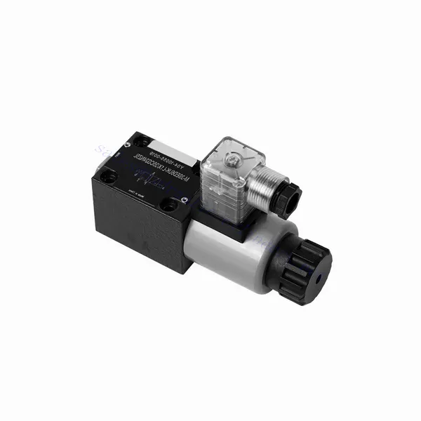
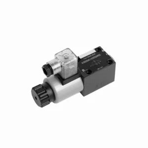
M-SED Series Directional Poppet Hydraulic Valve With Solenoid Actuation
Som en av produsentene, leverandørene og eksportørene av mekaniske produkter tilbyr vi hydrauliske sylindere og mange andre produkter.
Ta kontakt med oss for mer informasjon.
Post:sales@hydraulic-cylinders.net
Produsent, leverandør og eksportør av hydrauliske sylindere.
M-SED Series Directional Poppet Hydraulic Valve With Solenoid Actuation
The M-SED series directional poppet hydraulic valve with solenoid actuation is a cutting-edge solution that provides precise control and optimal efficiency in hydraulic systems. With its innovative design, reliable performance, and advanced solenoid actuation, this valve offers enhanced fluid flow control, flexibility, and compatibility with various industrial applications.
The M-SED series directional poppet hydraulic valve with solenoid actuation is a reliable and efficient solution for hydraulic systems. With its directional poppet design, advanced solenoid actuation, versatility, and high flow capacity, this valve offers precise control, enhanced efficiency, and compatibility with various applications. The M-SED series valve delivers optimal performance and reliability by following the recommended usage methods and adhering to regular maintenance practices. Upgrade your hydraulic system with the M-SED series directional poppet hydraulic valve and experience enhanced control, efficiency, and productivity.
M-SED Series Directional Poppet Hydraulic Valve With Solenoid Actuation Key Characteristics:
- Directional Poppet Design:
- The M-SED series valve features a directional poppet design, ensuring reliable and efficient fluid flow control.
- It allows for quick response times and precise regulation of fluid direction, enhancing overall system performance.
- Magnetaktivering:
- This hydraulic valve is equipped with advanced solenoid actuation and provides remote and automated control capabilities.
- The solenoid allows quick and accurate switching between different flow paths, improving operational efficiency.
- Allsidighet og kompatibilitet:
- The M-SED series valve is highly versatile and compatible with various hydraulic systems and applications.
- It can be seamlessly integrated into industrial machinery, mobile equipment, and automation systems, enhancing performance.
- Høy strømningskapasitet:
- With its robust design and optimized flow paths, the M-SED series valve offers high flow capacity.
- It ensures efficient fluid transfer, reducing pressure drops and maximizing system throughput.
M-SED Series Directional Poppet Hydraulic Valve With Solenoid Actuation Parameter:
| Spesifikasjoner | NG6 | NG10 | ||
| Installasjonsposisjon | Valgfri | |||
| Omgivelsestemperatur | ℃ | -30 til +50 (NBR-tetninger) | ||
| -20 til +50 (FKM-tetninger) | ||||
| Vekt | Two three-way solenoidic directional valve | kg | 1.5 | 2.6 |
| Two four-way solenoidic directional valve | kg | 2.3 | 3.9 | |
| Maks. driftstrykk | bar | 350 | 350 | |
| Maks. strømningshastighet | l/min | 25 | 40 | |
| Væske | Mineralolje egnet for NBR- og FKM-tetninger | |||
| Fosfatester for FKM-tetning | ||||
| Væsketemperaturområde | ℃ | -30 til +80 (NBR-tetninger) | ||
| -20 til +80 (FKM-tetninger) | ||||
| Viskositetsområde | mm2/s | 2,8 til 500 | ||
| Grad av forurensning | Maximum permissible degree of fluid contamination: Class 9. NAS 1638 | Maksimal tillatt grad av væskeforurensning: Klasse 9. NAS 1638 eller 20/18/15, ISO4406 | ||
M-SED Series Directional Poppet Hydraulic Valve With Solenoid Actuation Advantages:
• Direct solenoid shutoff valve
• Monteringsflaten følger DIN 24340 A, ISO 4401 og CETOP-RP 121H
• No leak
• Responsive switching under high pressure
• Det er ikke nødvendig å åpne det forseglede kammeret for å bytte ut spolen
• Magnetspolen kan roteres 90°
• With manual emergency control optional
Usage Method Of M-SED Series Directional Poppet Hydraulic Valve With Solenoid Actuation:
- Systemvurdering:
- Conduct a thorough assessment of the hydraulic system to determine the specific requirements and operational parameters.
- Consider factors such as flow rates, pressure ratings, and compatibility with the M-SED Series Valve.
- Ventilvalg:
- Select the appropriate M-SED Series Valve variant based on the system requirements and specifications.
- Consider factors such as port size, voltage compatibility, and solenoid actuation parameters.
- Installasjon:
- Follow the manufacturer’s instructions for proper installation of the M-SED Series Valve in the hydraulic system.
- Ensure secure mounting, proper alignment, and appropriate sealing to prevent leaks and ensure optimal performance.
- Elektriske tilkoblinger:
- Connect the solenoid actuation wires to a suitable power source, following the recommended wiring guidelines.
- Ensure proper polarity and insulation to prevent electrical malfunctions or safety hazards.
How Does A Hydraulic Counterbalance Valve Work?
A hydraulic counterbalance valve is a type of valve used in hydraulic systems to control the motion and stability of loads. It is commonly employed in applications where there is a need to control the descent or lowering of heavy loads, such as in cranes, excavators, and material handling equipment. The primary function of a counterbalance valve is to provide controlled resistance to the downward movement of a load, preventing it from free-falling or dropping uncontrollably.
Here’s how a hydraulic counterbalance valve works:
- Flytkontroll:
- When the load is lifted, hydraulic fluid flows from the pump to the cylinder, raising the load.
- The counterbalance valve is installed in the line between the cylinder and the directional control valve.
- Check Valve Function:
- The counterbalance valve incorporates a built-in check valve that allows the free flow of oil from the pump to the cylinder during the lifting phase.
- The check valve opens, permitting fluid flow in one direction while blocking it in the opposite direction.
- Counterbalance Function:
- When the lifting action is complete and the directional control valve is shifted to the neutral position, the counterbalance valve comes into play.
- As the load starts to descend, the pressure at the cylinder port of the counterbalance valve increases.
- Pilot Pressure:
- The increased pressure at the cylinder port acts on a pilot piston within the counterbalance valve.
- This pilot pressure opposes the spring force in the valve, causing the valve to open gradually.
- Flow Restriction:
- As the counterbalance valve opens, it creates a restricted flow path for the hydraulic fluid returning from the cylinder.
- This restriction slows down the rate of fluid flow, providing controlled resistance against the load’s downward motion.
- Load Control:
- The counterbalance valve modulates the flow restriction based on the load’s weight and the desired speed of descent.
- By adjusting the spring tension or using adjustable counterbalance valves, the valve’s setting can be customized for specific applications.
- Stability and Safety:
- The counterbalance valve ensures stability and safety by preventing the load from dropping too quickly or causing uncontrolled movements.
- It maintains the load in a stable position, even when external forces or variations in the hydraulic system occur.
Fabrikkens kapasitet og kapasitet:
(1) Montering
Vi har en førsteklasses uavhengig forsknings- og utviklingsplattform for montering. Verkstedet for produksjon av hydrauliske sylindere har fire halvautomatiske monteringslinjer for løftesylindere og én automatisk monteringslinje for vippesylindere, med en årlig produksjonskapasitet på 1 million enheter. Spesialsylinderverkstedet er utstyrt med ulike spesifikasjoner for et halvautomatisk rengjøringsmonteringssystem med en årlig produksjonskapasitet på 200 000 enheter, og er utstyrt med kjent CNC-maskineringsutstyr, et maskineringssenter, spesialutstyr for høypresisjons sylinderbehandling, en robotsveisemaskin, en automatisk rengjøringsmaskin, en automatisk sylindermonteringsmaskin og en automatisk produksjonslinje for lakkering. Vi har mer enn 300 sett (sett) av kritisk utstyr. Optimal allokering og effektiv bruk av utstyrsressurser sikrer nøyaktighetskravene til produktene og oppfyller produktenes høye kvalitetsbehov.


(2) Maskinering
Maskineringsverkstedet er utstyrt med et spesialtilpasset dreiesenter for skrå skinner, maskineringssenter, høyhastighets honemaskin, sveiserobot og annet relatert utstyr, som kan håndtere bearbeiding av sylinderrør med en maksimal indre diameter på 400 mm og en maksimal lengde på 6 meter.

(3) Sveising

(4) Maling og belegg
Med små og mellomstore sylinderautomatiske vannbaserte malingsbeleggslinjer, for å oppnå automatisk robotlasting og -lossing og automatisk sprøyting, er den designede kapasiteten 4000 stykker per skift;
Vi har også en halvautomatisk produksjonslinje for maling for store sylindere drevet av en kabelkjede, med en designkapasitet på 60 kasser per skift.


(5) Testing
Vi har førsteklasses inspeksjonsfasiliteter og testbenker for å sikre at sylinderens ytelse oppfyller kravene.

Vi er en av de beste produsentene av hydrauliske sylindere. Vi kan tilby et omfattende utvalg av hydrauliske sylindere. Vi tilbyr også tilsvarende landbruksgirkasserVi har eksportert produktene våre til kunder over hele verden og opparbeidet oss et godt rykte på grunn av vår overlegne produktkvalitet og ettersalgsservice. Vi ønsker kunder i inn- og utland velkommen til å kontakte oss for å forhandle om forretninger, utveksle informasjon og samarbeide med oss!
Hydraulisk sylinderapplikasjon:
