WMM Series Directional Hydraulic Valve With Mechanical, Manual Operation
WMM Series Directional Hydraulic Valve With Mechanical, Manual Operation
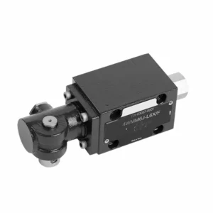
The WMM series directional hydraulic valve with mechanical, manual operation is a versatile and reliable solution designed to control hydraulic systems precisely. This hydraulic valve offers enhanced efficiency and flexibility with its advanced features and robust construction.
The WMM series directional hydraulic valve with mechanical, manual operation is a reliable and versatile solution for hydraulic systems. Its automatic manual operation and precise directional control offer enhanced flexibility and control for various applications. Following the recommended usage methods and adhering to regular maintenance practices, the WMM series hydraulic valve will continue providing efficient and reliable operation. Upgrade your hydraulic system with the WMM series directional valve and experience the benefits of enhanced control and versatility.
WMM Series Directional Hydraulic Valve With Mechanical, Manual Operation Key Characteristics:
- Mechanical, Manual Operation:
- The WMM series hydraulic valve features a mechanical, manual operation, allowing operators to control the valve position manually.
- This provides flexibility and control in applications where manual operation is desired or required.
- Retningskontroll:
- This hydraulic valve enables precise directional fluid flow control within the hydraulic system.
- It allows operators to select the desired flow path, ensuring efficient and reliable operation.
- Slitesterk konstruksjon:
- The WMM series hydraulic valve is constructed with high-quality materials, ensuring durability and longevity.
- Its robust design can withstand demanding operating conditions, providing reliable performance.
- Kompakt størrelse:
- The valve’s compact size allows easy integration into hydraulic systems with limited space.
- It is ideal for applications where space is a constraint without compromising performance.
WMM Series Directional Hydraulic Valve With Mechanical, Manual Operation Parameter:
NG6
| Væsketemperaturområde | ℃ | -30 til +80 (NBR-tetninger) | |
| -20 til +80 (FKM-tetninger) | |||
| Maks. driftstrykk for port | Port ABP | bar | 315 |
| Port T | bar | 160 | |
| Maks. strømningshastighet | l/min | 60 | |
| Strømningsområde (bytter nøytral posisjon) | Q-typen | mm2 | For symbol Q, 6% av det nominelle tverrsnittet |
| W-typen | mm2 | For symbolet W, 3% av det nominelle tverrsnittet | |
| Væske | Mineralolje; Fosfatester | ||
| Viskositetsområde | mm2/s | 2,8 til 500 | |
| Grad av forurensning | Maksimal tillatt grad av væskeforurensning: Klasse 9. NAS 1638 eller 20/18/15, ISO4406 | ||
| Vekt | kg | 1.6 | |
NG10
| Væsketemperaturområde | ℃ | -30 til +80 (NBR-tetninger) | |
| -20 til +80 (FKM-tetninger) | |||
| Maks. driftstrykk for port | Port ABP | bar | 315 |
| Port T | bar | 160 | |
| Maks. strømningshastighet | l/min | 120 | |
| Strømningstverrsnitt (brytende nøytral posisjon) | V-typen | mm2 | 11(A/B → T);10,3(P → A/B) |
| W-typen | mm2 | 2,5 (A/B → T) | |
| Q-typen | mm2 | 5,5 (A/B → T) | |
| Væske | Mineralolje; Fosfatester | ||
| Viskositetsområde | mm2/s | 2,8 til 500 | |
| Grad av forurensning | Maksimal tillatt grad av væskeforurensning: Klasse 9. NAS 1638 eller 20/18/15, ISO4406 | ||
| Vekt | kg | 4.4 | |
NG16-32
| NS | 16 | 25 | 32 |
| Vekt | about 8 | about 12.2 | about 49 |
| Actuation force with detent N | about 75 | about 105 | about 170 |
| with spring return N | |||
| Actuation angle about the neutral position | 2*26° | 2*32° | 2*30° |
| Max. operating pressure Port A,B,P bar | 315 | ||
| Port T bar | 250 | ||
| Væske | Mineralolje egnet for NBR- og FKM-tetninger | ||
| Phosphate ester – for FKM seal | |||
| Væsketemperaturområde | -30 to +80(NBR seal) | ||
| -20 til +80 (FKM-tetning) | |||
| Viscosity range mm2/s | 2.8 to 380 | ||
| Grad av forurensning | Maksimal tillatt grad av væskeforurensning: Klasse 9. NAS 1638 eller 20/18/15, ISO4406 | ||
WMM Series Directional Hydraulic Valve With Mechanical, Manual Operation Advantages:
• Direktevirkende retningsskyveventil direktevirkende retningsskyveventil
• Sub-plate mounting
• Handle control
• Installation face follow DIN 24340 A, ISO 4401
Usage Method Of WMM Series Directional Hydraulic Valve With Mechanical, Manual Operation:
- Systemintegrasjon:
- Identify the appropriate location for the WMM series hydraulic valve within the hydraulic system, considering the desired flow direction and control requirements.
- Sørg for kompatibilitet med systemets trykk- og strømningsspesifikasjoner.
- Monter ventilen sikkert med passende braketter eller monteringstilbehør.
- Væsketilkoblinger:
- Velg kompatible hydrauliske koblinger og slanger for sikre og lekkasjefrie tilkoblinger.
- Følg produsentens instruksjoner for riktig momentverdi under installasjonsprosessen.
- Bruk passende gjengetetningsmidler eller tape for å sikre en pålitelig tetning.
- Manual Operation:
- Familiarize yourself with the manual operation mechanism of the valve, including the lever or knob used to control the hydraulic valve position.
- Ensure the operator understands the correct procedure for manually adjusting the valve position.
- Systemkalibrering:
- Calibrate the hydraulic valve position and movement according to the desired flow direction and control requirements.
- Adjust the valve manually to achieve the desired flow path and ensure proper functionality.
How To Adjust Valves On A Hydraulic Roller Cam?
Adjusting valves on a hydraulic roller cam requires careful attention to detail and following the proper procedure. Here’s a step-by-step guide to help you adjust the valves correctly:
- Prepare the Engine:
- Ensure the engine is turned off and cool to the touch before starting the adjustment process.
- Locate the valve covers and remove them to access the valve train components.
- Identify the Correct Valve Adjustment Sequence:
- Consult the engine manufacturer’s specifications or service manual to determine the correct valve adjustment sequence for your specific engine.
- Locate the Top Dead Center (TDC) Position:
- Rotate the engine’s crankshaft in the normal direction of rotation until the number one piston reaches the top dead center position on its compression stroke.
- Use a timing mark on the harmonic balancer or flywheel and a timing pointer to identify the TDC position accurately.
- Adjusting Valve Lash:
- Begin with the first cylinder in the valve adjustment sequence.
- Loosen the lock nut on the rocker arm stud using an appropriate wrench or socket.
- Use a feeler gauge of the recommended thickness specified by the engine manufacturer to check the valve lash (clearance) between the rocker arm and the valve stem.
- Slide the feeler gauge between the rocker arm and the valve stem. You should feel slight resistance but still be able to move the gauge back and forth.
- Adjust the valve lash by either tightening or loosening the rocker arm stud until the proper clearance is achieved. Turning the stud clockwise decreases the clearance, while counterclockwise increases it.
- Once you’ve set the correct valve lash, hold the rocker arm stud in place and tighten the lock nut securely.
- Gjenta prosessen:
- Move to the next cylinder in the valve adjustment sequence and repeat steps 4 and 5 until all the valves have been adjusted.
- Reinstall Valve Covers:
- Once you’ve completed the valve adjustment on all cylinders, reinstall the valve covers and ensure they are properly sealed to prevent oil leaks.
- Double-Check:
- After adjusting the valves, it’s a good practice to go through the entire valve adjustment sequence once more to confirm that all clearances are within the specified range.
Fabrikkens kapasitet og kapasitet:
(1) Montering
Vi har en førsteklasses uavhengig forsknings- og utviklingsplattform for montering. Verkstedet for produksjon av hydrauliske sylindere har fire halvautomatiske monteringslinjer for løftesylindere og én automatisk monteringslinje for vippesylindere, med en årlig produksjonskapasitet på 1 million enheter. Spesialsylinderverkstedet er utstyrt med ulike spesifikasjoner for et halvautomatisk rengjøringsmonteringssystem med en årlig produksjonskapasitet på 200 000 enheter, og er utstyrt med kjent CNC-maskineringsutstyr, et maskineringssenter, spesialutstyr for høypresisjons sylinderbehandling, en robotsveisemaskin, en automatisk rengjøringsmaskin, en automatisk sylindermonteringsmaskin og en automatisk produksjonslinje for lakkering. Vi har mer enn 300 sett (sett) av kritisk utstyr. Optimal allokering og effektiv bruk av utstyrsressurser sikrer nøyaktighetskravene til produktene og oppfyller produktenes høye kvalitetsbehov.


(2) Maskinering
Maskineringsverkstedet er utstyrt med et spesialtilpasset dreiesenter for skrå skinner, maskineringssenter, høyhastighets honemaskin, sveiserobot og annet relatert utstyr, som kan håndtere bearbeiding av sylinderrør med en maksimal indre diameter på 400 mm og en maksimal lengde på 6 meter.

(3) Sveising

(4) Maling og belegg
Med små og mellomstore sylinderautomatiske vannbaserte malingsbeleggslinjer, for å oppnå automatisk robotlasting og -lossing og automatisk sprøyting, er den designede kapasiteten 4000 stykker per skift;
Vi har også en halvautomatisk produksjonslinje for maling for store sylindere drevet av en kabelkjede, med en designkapasitet på 60 kasser per skift.


(5) Testing
Vi har førsteklasses inspeksjonsfasiliteter og testbenker for å sikre at sylinderens ytelse oppfyller kravene.

Vi er en av de beste produsentene av hydrauliske sylindere. Vi kan tilby et omfattende utvalg av hydrauliske sylindere. Vi tilbyr også tilsvarende landbruksgirkasserVi har eksportert produktene våre til kunder over hele verden og opparbeidet oss et godt rykte på grunn av vår overlegne produktkvalitet og ettersalgsservice. Vi ønsker kunder i inn- og utland velkommen til å kontakte oss for å forhandle om forretninger, utveksle informasjon og samarbeide med oss!