
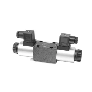
4WRA(E) Series Direct operated Proportional Directional Hydraulic Valve
4WRA(E) Series Direct operated Proportional Directional Hydraulic Valve
The 4WRA(E) series direct operated proportional directional hydraulic valve is a state-of-the-art hydraulic component designed to provide precise control and efficient operation in hydraulic systems. With its direct-operated proportional directional control technology, this valve offers accurate flow control, seamless direction changes, and optimized performance.
The 4WRA(E) series direct operated proportional directional hydraulic valve empowers hydraulic systems with precise flow control, versatile directional changes, and optimal energy efficiency. Its direct-operated proportional control technology ensures accurate and responsive operation, while the high flow capacity and energy-efficient design contribute to enhanced system performance. By following the recommended usage methods and maintenance guidelines, you can maximize the benefits and longevity of the 4WRA(E) series valve, elevating your hydraulic system to new levels of precision and efficiency. Upgrade your hydraulic setup today and experience the power of the 4WRA(E) series direct operated proportional directional hydraulic valve.
4WRA(E) Series Direct operated Proportional Directional Hydraulic Valve Key Characteristics:
- Direct Operated Proportional Control:
- The 4WRA(E) series valve utilizes direct-operated proportional control, allowing for precise and immediate response to control signals.
- This feature ensures accurate flow control and seamless transitions between different hydraulic functions.
- Hoge stroomcapaciteit:
- With its robust design, the valve offers high flow capacity, making it suitable for applications requiring substantial hydraulic power.
- It allows for efficient handling of large fluid volumes, contributing to enhanced system performance.
- Versatile Directional Control:
- The 4WRA(E) series valve provides versatile directional control, enabling smooth and precise changes in hydraulic fluid direction.
- It allows for the seamless activation of hydraulic components such as cylinders, motors, and actuators in different directions.
- Energie-efficiëntie:
- Designed with energy efficiency in mind, this valve minimizes pressure drops and optimizes flow control, resulting in reduced energy consumption.
- By efficiently managing hydraulic power, it helps maximize system performance while minimizing operational costs.
4WRA(E) Series Direct operated Proportional Directional Hydraulic Valve Parameter:
| Hydraulisch | ||||||||
| Installatiepositie | optioneel, bij voorkeur horizontaal | |||||||
| Maat | 6 | 10 | ||||||
| Gewicht | 4WRA…L2X | kg | 2 | 6.6 | ||||
| 4WRAE…L2X | 2.2 | 6.8 | ||||||
| Nominale stroom qnom, wanneer Δp = 10 bar | L/min | 7, 15 en 26 | 30, 60 | |||||
| Hysterese | % | ≤5 | ||||||
| Herhaalbaarheid | % | ≤1 | ||||||
| Responsgevoeligheid | % | ≤0,5 | ||||||
| Maximale werkdruk | Port s ABP | bar | 315 | |||||
| Poort T | bar | 210 | ||||||
| Vloeistof | Minerale olie geschikt voor NBR- en FKM-afdichting | |||||||
| Fosfaatester voor FKM-afdichting | ||||||||
| Vloeistoftemperatuurbereik | 4WRA…L2X | ℃ | -20℃ tot 70℃(-4°F tot 158°F) | |||||
| 4WRAE…L2X | ℃ | -20℃ tot 50℃(-4° F tot 122° F) | ||||||
| Viscositeitsbereik | mm²/s | 20 tot 380 (bij voorkeur 30 tot 46) | ||||||
| Mate van verontreiniging | NAS1638 klasse 9 of ISO 4406 klasse 20/18/15 | |||||||
| Elektrische gegevens | ||||||||
| 1)solenoïde | ||||||||
| Spanningstype | gelijkstroom | |||||||
| Commandowaardesignaal | ±10V of 4~20mA | |||||||
| Max. stroom per solenoïde | A | 2.5 | 1.5 | 0.8 | ||||
| Spoelweerstand | Koude waarde | Ω | 2 | 4.8 | 19.5 | |||
| Maximale warme waarde | 3 | 7.2 | 28.8 | |||||
| Plicht | % | ED100% | ||||||
| Spoeltemperatuur | ℃ | 150 | ||||||
| Klepbescherming volgens EN 60529 | IP 65 | |||||||
| 2) Besturingselektronica | ||||||||
| Versterker | 4WRA…L2X | VT-VSPA2-L2X | ||||||
| 4WRAE…L2X | Geïntegreerd in de klep (OBE) | |||||||
| Bedrijfsspanning | Nominale spanning | VDC | 24 | |||||
| Ondergrenswaarde | V | 21/22(4WRA), 19(4WRAE) | ||||||
| Bovengrenswaarde | V | 35 | ||||||
| Stroomverbruik van de versterker | Imax | A | <1,8 | |||||
| Imax | A | 3 | ||||||
4WRA(E) Series Direct operated Proportional Directional Hydraulic Valve Advantages:
• Direct-acting proportional directional valve, used to control the flow and direction of liquid flow
• Panel type installation
• The proportional solenoid actuates the valve core through the threaded connection, and the coil can be removed separately
• Spool spring alignment alignment
• Optional with built-in amplifier, 4WRAE…L2X type input can be A1 or F1
• Supporting supply of external amplifier
Usage Method Of 4WRA(E) Series Direct operated Proportional Directional Hydraulic Valve:
- Systeemevaluatie:
- Evaluate your hydraulic system and identify the specific flow control and directional requirements.
- Determine if the 4WRA(E) series valve is suitable based on its flow capacity, pressure rating, and compatibility with your system.
- Klepselectie:
- Select the appropriate variant of the 4WRA(E) series valve based on your system parameters, flow requirements, and directional control needs.
- Consider factors such as maximum flow rate, pressure rating, response time, and operational conditions.
- Installatie:
- Volg de installatie-instructies van de fabrikant nauwkeurig op en zorg voor een juiste uitlijning en stevige montage van de klep.
- Sluit de klep aan op het hydraulische systeem en zorg ervoor dat er geen lekkage is en dat de stroomrichting correct is.
- Control Signal Connection:
- Connect the control signal wires of the valve to the appropriate control device, such as a proportional amplifier or electronic control unit.
- Ensure proper wiring and compatibility between the valve and the control device to enable accurate and responsive control.
How To Adjust Valve Lash On Hydraulic Lifters?
Adjusting valve lash on hydraulic lifters is a crucial maintenance task to ensure proper engine performance and prevent issues such as noisy valves or reduced power. Here’s a step-by-step guide on how to adjust valve lash on hydraulic lifters:
- Voorbereiding:
- Ensure the engine is off and cool before starting the adjustment process.
- Familiarize yourself with the engine’s firing order and the specific valve lash specifications provided by the manufacturer for your engine model.
- Identify the Correct Cylinder:
- Locate the firing position of the engine by referring to the engine’s firing order diagram.
- Identify the cylinder that corresponds to the specific valve you want to adjust.
- Plaats de cilinder:
- Rotate the engine crankshaft manually using a socket wrench or the engine’s built-in turning mechanism.
- Position the cylinder you want to adjust at the top dead center (TDC) on the compression stroke. You can do this by aligning the timing marks on the crankshaft pulley or using a piston stop tool.
- Loosen the Rocker Arm:
- Locate the rocker arm on the specific valve you want to adjust.
- Loosen the rocker arm nut or adjuster screw using an appropriate wrench or socket.
- Adjust the Valve Lash:
- With the rocker arm loose, you can now adjust the valve lash. The valve lash is the clearance between the rocker arm and the valve stem.
- Use a feeler gauge to measure the existing valve lash. Insert the appropriate thickness gauge between the rocker arm and the valve stem.
- If the clearance is too tight, meaning the feeler gauge does not fit or has excessive resistance, you need to increase the valve lash. If the clearance is too loose, meaning the feeler gauge slides in too easily, you need to decrease the valve lash.
- To adjust the valve lash, tighten or loosen the rocker arm nut or adjuster screw accordingly. Refer to the manufacturer’s specifications for the recommended amount of adjustment to be made.
- Recheck the Valve Lash:
- After making the adjustment, recheck the valve lash using the feeler gauge to ensure it falls within the recommended specifications.
- Repeat the adjustment process if necessary until the correct valve lash is achieved.
- Repeat for Other Cylinders:
- Proceed to the next cylinder in the firing order and repeat steps 4 to 6 for each cylinder you want to adjust.
- Remember to rotate the crankshaft and position each cylinder at TDC on the compression stroke before adjusting its valve lash.
- Secure the Rocker Arm:
- Once the valve lash is properly adjusted for each cylinder, tighten the rocker arm nut or adjuster screw to the manufacturer’s recommended torque specification.
- Double-check that the valve lash remains within the specified range after tightening.
- Final Checks:
- Rotate the engine crankshaft a few times to ensure smooth rotation and check for any unusual noises or resistance.
- Start the engine and listen for any abnormal valve noises. If you hear excessive tapping or knocking, recheck the valve lash adjustment.
Vermogen en capaciteit van de fabriek:
(1) Montage
We beschikken over een eersteklas, onafhankelijk R&D-platform voor assemblage. De productiewerkplaats voor hydraulische cilinders beschikt over vier semi-automatische hefcilinderassemblagelijnen en één automatische kantelcilinderassemblagelijn, met een geplande jaarlijkse productiecapaciteit van 1 miljoen stuks. De speciale cilinderwerkplaats is uitgerust met diverse specificaties van een semi-automatisch reinigingsassemblagesysteem met een geplande jaarlijkse productiecapaciteit van 200.000 stuks en is uitgerust met gerenommeerde CNC-bewerkingsapparatuur, een bewerkingscentrum, een zeer nauwkeurige cilinderbewerkingsapparatuur, een robotlasmachine, een automatische reinigingsmachine, een automatische cilinderassemblagemachine en een automatische verfproductielijn. De bestaande kritische apparatuur bestaat uit meer dan 300 sets. De optimale toewijzing en het efficiënte gebruik van apparatuur garanderen de nauwkeurigheidseisen van producten en voldoen aan de hoge kwaliteitseisen.


(2) Bewerking
De bewerkingsruimte is uitgerust met een op maat gemaakt schuin rails draaicentrum, bewerkingscentrum, hogesnelheids hoonmachine, lasrobot en andere bijbehorende apparatuur, die de bewerking van cilinderbuizen met een maximale binnendiameter van 400 mm en een maximale lengte van 6 meter aankan.

(3) Lassen

(4) Schilderen en coaten
Met kleine en middelgrote automatische cilindercoatinglijnen voor watergedragen verf, om automatisch laden en lossen door robots en automatisch spuiten te bereiken, is de ontwerpcapaciteit 4000 stuks per ploegendienst;
Ook beschikken wij over een semi-automatische verfproductielijn voor grote cilinders, aangedreven door een kabelrups, met een ontwerpcapaciteit van 60 dozen per ploeg.


(5) Testen
Wij beschikken over eersteklas inspectiefaciliteiten en testbanken om te garanderen dat de prestaties van de cilinder aan de eisen voldoen.

Wij zijn een van de beste fabrikanten van hydraulische cilinders. We bieden een compleet assortiment hydraulische cilinders. Ook leveren we bijbehorende onderdelen. landbouwversnellingsbakkenWe hebben onze producten wereldwijd geëxporteerd en een goede reputatie opgebouwd dankzij onze superieure productkwaliteit en aftersalesservice. We nodigen klanten in binnen- en buitenland uit om contact met ons op te nemen om zaken te doen, informatie uit te wisselen en werk met ons samen!


