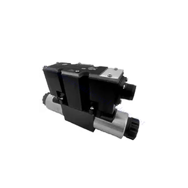
3DREP(E) Series 3-way Proportional Pressure Reducing Hydraulic Valve
Als één van de fabrikanten, de leveranciers en de exporteurs van van de hydraulische cilinders mechanische producten, bieden wij hydraulische cilinders en veel andere producten aan.
Neem contact met ons op voor meer informatie.
Mail:sales@hydraulic-cylinders.net
Fabrikant leverancier exporteur van hydraulische cilinders.
3DREP(E) Series 3-way Proportional Pressure Reducing Hydraulic Valve
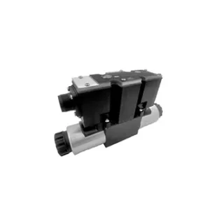
The 3DREP(E) series 3-way proportional pressure-reducing hydraulic valve is a state-of-the-art hydraulic component specifically engineered to provide accurate pressure control in hydraulic systems. With its advanced proportional control technology, this valve ensures precise regulation, efficiency, and reliable performance.
The 3DREP(E) series 3-way proportional pressure-reducing hydraulic valve empowers hydraulic systems with precise pressure control, efficiency, and reliable performance. With its advanced proportional control technology and 3-way configuration, this valve offers versatility and flexibility in pressure regulation across different hydraulic circuits. By following the recommended usage methods and maintenance guidelines, you can maximize the benefits and longevity of the 3DREP(E) series valve, optimizing pressure control and overall performance in your hydraulic system. Upgrade your hydraulic setup today and experience superior pressure regulation with the 3DREP(E) series 3-way proportional pressure-reducing hydraulic valve.
3DREP(E) Series 3-way Proportional Pressure Reducing Hydraulic Valve Key Characteristics:
- Proportionele drukregeling:
- The 3DREP(E) series valve offers precise and proportional pressure control, allowing for dynamic adjustment of hydraulic pressure levels.
- It ensures accurate pressure regulation, maintaining consistent and safe pressure within the hydraulic system.
- 3-weg configuratie:
- This valve features a 3-way configuration, providing versatility and flexibility in controlling pressure across different hydraulic circuits.
- It allows for the simultaneous reduction of pressure in one circuit while supplying pressure to another circuit.
- Verbeterde systeemefficiëntie:
- With its proportional control technology, the 3DREP(E) series valve enabled precise pressure adjustment, resulting in enhanced system efficiency and reduced energy consumption.
- By maintaining optimal pressure levels, it minimizes pressure fluctuations, optimizes system performance, and lowers operational costs.
- Betrouwbare prestaties:
- The 3DREP(E) series valve is designed to deliver consistent and reliable performance under varying operating conditions.
- It ensures stable pressure control, reducing the risk of system failures, component damage, and potential downtime.
3DREP(E) Series 3-way Proportional Pressure Reducing Hydraulic Valve Parameter:
| Hydraulisch | ||||
| Specificaties | 3DREP6…L2X | 3DREPE6…L2X | ||
| Installatiepositie | Optional, preferably horizontal | |||
| Gewicht | KG | 2 | 2.2 | |
| Omgevingstemperatuurbereik | ℃ | -20 tot +70 | -20 to +50 | |
| Max. debiet | L/min | 15 (Δp = 50 bar) | ||
| Hysterese | % | ≤5 | ||
| Herhaalbaarheid | % | ≤1 | ||
| Responsgevoeligheid | % | ≤0,5 | ||
| Maximale werkdruk | Port P | bar | 20 to 100,pressure stage 16 | |
| 30 to 100,pressure stage 25 | ||||
| 50 to 100,pressure stage 45 | ||||
| Poort T | 0 to 3 | |||
| Vloeistof | Minerale olie geschikt voor NBR- en FKM-afdichting | |||
| Fosfaatester voor FKM-afdichting | ||||
| Vloeistoftemperatuurbereik | ℃ | -20 to +80 | ||
| Viscositeitsbereik | mm2/S | 20 to 380 (preferably 30 to 46) | ||
| Mate van verontreiniging | Maximum permissible degree of fluid contamination: Class 9 and ISO4406 Class 20/18/15 | |||
| Elektrische gegevens | ||||
| solenoid | ||||
| Specificaties | 3DREP6…L2X | 3DREPE6…L2X | ||
| Elektrische gegevens | gelijkstroom | |||
| Commandowaardesignaal | – | ±10V | ||
| Max. stroom per solenoïde | A | 1.5 | 2.5 | |
| Spoelweerstand | Cold value at 20 ℃ | Ω | 4.8 | 2 |
| Maximale warme waarde | 7.2 | 3 | ||
| Plicht | % | ED100% | ||
| Spoeltemperatuur | ℃ | to 150 | ||
| Klepbescherming volgens EN 60529 | IP 65 | |||
| Versterker | VT-VSPA2-50-L1X | integrated | ||
| Bedrijfsspanning | Nominale spanning | VDC | 24 | |
| Ondergrenswaarde | V | 19 | ||
| Bovengrenswaarde | V | 35 | ||
| Stroomverbruik van de versterker | Imax | A | 1.8 | |
| Imax | A | 4 | ||
Voordelen van de 3DREP(E)-serie 3-weg proportionele drukreducerende hydraulische klep:
• Direct-acting proportional valve, used to control pressure and flow direction
• Panel type installation
• The valve core is actuated by the proportional solenoid through the threaded connection, and the coil can be removed separately
• Spool spring alignment alignment
• Optional with built-in amplifier, 3DREPE6…L2X type input interface A1 or F1
• Supporting supply of external amplifier
Gebruiksmethode van 3DREP(E)-serie 3-weg proportionele drukreducerende hydraulische klep:
- Systeemevaluatie:
- Evalueer uw hydraulisch systeem en identificeer de specifieke drukregelvereisten voor elk circuit.
- Determine if the 3DREP(E) series valve is suitable based on its pressure range, flow capacity, and compatibility with your system.
- Klepselectie:
- Choose the appropriate variant of the 3DREP(E) series valve based on your system parameters, pressure range, and flow requirements.
- Houd rekening met de maximale druk, de reactietijd en de bedrijfsomstandigheden.
- Installatie:
- Volg de installatie-instructies van de fabrikant nauwkeurig op en zorg voor een juiste uitlijning en stevige montage van de klep.
- Sluit de klep aan op het hydraulische systeem en zorg ervoor dat er geen lekkage is en dat de stroomrichting correct is.
- Drukregeling:
- Utilize the proportional control signal or adjustment mechanism provided with the 3DREP(E) series valve to set the desired pressure reduction level for each circuit.
- Stel de klep stapsgewijs bij, onder controle van de drukmeterwaarden en de reactie van het systeem, om een nauwkeurige drukregeling te bereiken.
How To Adjust Hydraulic Relief Valve?
Adjusting a hydraulic relief valve is an important task to ensure proper pressure regulation and system performance in hydraulic applications. Here’s a step-by-step guide on how to adjust a hydraulic relief valve:
- Identify the Relief Valve:
- Locate the relief valve in your hydraulic system. It is typically positioned near the pump or in the pressure line.
- Verzamel de benodigde hulpmiddelen:
- Before starting the adjustment process, gather the required tools, such as a pressure gauge, an adjustable wrench, and a screwdriver.
- Measure the Current Pressure:
- Connect the pressure gauge to a test port or the outlet of the relief valve. Make sure the gauge is rated for the system’s operating pressure.
- Activate the hydraulic system and observe the pressure reading on the gauge. This will provide a baseline for the adjustment process.
- Determine the Desired Pressure:
- Refer to the system specifications or consult the manufacturer’s guidelines to determine the desired pressure for your hydraulic system.
- Ensure that the relief valve’s pressure range suits the desired pressure setting.
- Prepare for Adjustment:
- Identify the adjustment mechanism on the relief valve. It can be a set screw, locknut, or a similar tool.
- Use an adjustable wrench or an appropriate tool to loosen the locknut, if present, without disturbing the adjustment screw.
- Adjust the Relief Valve:
- Turning the adjustment screw clockwise will increase the pressure setting, while turning it counterclockwise will decrease the pressure setting.
- Make small adjustments at a time, typically a quarter or half turn, to avoid abrupt changes in pressure.
- Monitor the pressure gauge while making adjustments and ensure that the pressure remains within the desired range.
- Vergrendel de afstelling:
- Once you achieve the desired pressure setting, tighten the locknut (if present) to secure the adjustment screw in place.
- Ensure that the adjustment screw is firmly tightened but avoid over-tightening, as it may affect the valve’s performance.
- Testen en verifiëren:
- Activate the hydraulic system and observe the pressure gauge to ensure that the relief valve maintains the desired pressure under normal operating conditions.
- Monitor the system for any abnormalities or pressure fluctuations. If necessary, make further adjustments to fine-tune the relief valve setting.
Vermogen en capaciteit van de fabriek:
(1) Montage
We beschikken over een eersteklas, onafhankelijk R&D-platform voor assemblage. De productiewerkplaats voor hydraulische cilinders beschikt over vier semi-automatische hefcilinderassemblagelijnen en één automatische kantelcilinderassemblagelijn, met een geplande jaarlijkse productiecapaciteit van 1 miljoen stuks. De speciale cilinderwerkplaats is uitgerust met diverse specificaties van een semi-automatisch reinigingsassemblagesysteem met een geplande jaarlijkse productiecapaciteit van 200.000 stuks en is uitgerust met gerenommeerde CNC-bewerkingsapparatuur, een bewerkingscentrum, een zeer nauwkeurige cilinderbewerkingsapparatuur, een robotlasmachine, een automatische reinigingsmachine, een automatische cilinderassemblagemachine en een automatische verfproductielijn. De bestaande kritische apparatuur bestaat uit meer dan 300 sets. De optimale toewijzing en het efficiënte gebruik van apparatuur garanderen de nauwkeurigheidseisen van producten en voldoen aan de hoge kwaliteitseisen.


(2) Bewerking
De bewerkingsruimte is uitgerust met een op maat gemaakt schuin rails draaicentrum, bewerkingscentrum, hogesnelheids hoonmachine, lasrobot en andere bijbehorende apparatuur, die de bewerking van cilinderbuizen met een maximale binnendiameter van 400 mm en een maximale lengte van 6 meter aankan.

(3) Lassen

(4) Schilderen en coaten
Met kleine en middelgrote automatische cilindercoatinglijnen voor watergedragen verf, om automatisch laden en lossen door robots en automatisch spuiten te bereiken, is de ontwerpcapaciteit 4000 stuks per ploegendienst;
Ook beschikken wij over een semi-automatische verfproductielijn voor grote cilinders, aangedreven door een kabelrups, met een ontwerpcapaciteit van 60 dozen per ploeg.


(5) Testen
Wij beschikken over eersteklas inspectiefaciliteiten en testbanken om te garanderen dat de prestaties van de cilinder aan de eisen voldoen.

Wij zijn een van de beste fabrikanten van hydraulische cilinders. We bieden een compleet assortiment hydraulische cilinders. Ook leveren we bijbehorende onderdelen. landbouwversnellingsbakkenWe hebben onze producten wereldwijd geëxporteerd en een goede reputatie opgebouwd dankzij onze superieure productkwaliteit en aftersalesservice. We nodigen klanten in binnen- en buitenland uit om contact met ons op te nemen om zaken te doen, informatie uit te wisselen en werk met ons samen!
Toepassing hydraulische cilinder:
