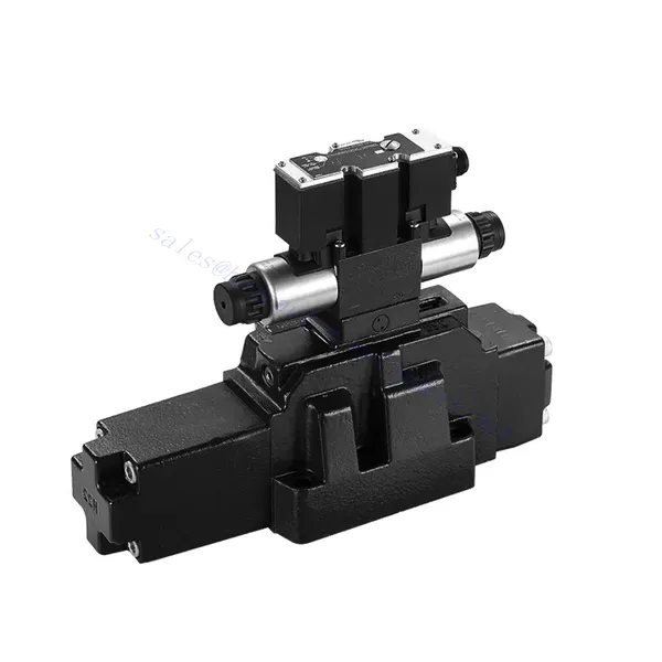
4WRZ/H(E) Series Pilot Operated Proportional Directional Hydraulic Valve
Als één van de fabrikanten, de leveranciers en de exporteurs van van de hydraulische cilinders mechanische producten, bieden wij hydraulische cilinders en veel andere producten aan.
Neem contact met ons op voor meer informatie.
Mail:sales@hydraulic-cylinders.net
Fabrikant leverancier exporteur van hydraulische cilinders.
4WRZ/H(E) Series Pilot Operated Proportional Directional Hydraulic Valve
The 4WRZ/H(E) series pilot-operated proportional directional hydraulic valve is a state-of-the-art component designed to provide exceptional precision, control, and efficiency in hydraulic systems. With its advanced pilot-operated proportional control technology, this valve enables accurate flow regulation and seamless directional changes.
The 4WRZ/H(E) series pilot-operated proportional directional hydraulic valve empowers hydraulic systems with precise flow control, versatile directional changes, and energy efficiency. Its pilot-operated proportional control technology ensures accurate and responsive flow adjustment, while the high flow capacity guarantees reliable performance even in demanding applications. By following the recommended usage methods and maintenance guidelines, you can maximize the benefits and longevity of the 4WRZ/H(E) series valve, elevating your hydraulic system to new levels of precision and control. Upgrade your hydraulic setup today and experience the power of the 4WRZ/H(E) series pilot-operated proportional directional hydraulic valve.
4WRZ/H(E) Series Pilot Operated Proportional Directional Hydraulic Valve Key Characteristics:
- Pilot-Operated Proportional Control
- The 4WRZ/H(E) series valve utilizes pilot-operated proportional control technology, allowing precise and proportional flow adjustment based on control signals.
- This feature ensures accurate and responsive control, resulting in improved system performance, reduced energy consumption, and enhanced productivity.
- Versatile Directional Control
- This valve offers versatile control over hydraulic fluid direction, making it suitable for a wide range of applications.
- It enables seamless activation and deactivation of hydraulic components such as cylinders, motors, and actuators in different directions, enhancing system flexibility and adaptability.
- High Flow Capacity
- The 4WRZ/H(E) series valve is engineered to handle high flow rates, making it ideal for applications that require substantial hydraulic power.
- Its robust construction ensures reliable performance even under demanding conditions, providing consistent and efficient flow control.
- Energie-efficiëntie
- By incorporating pilot-operated proportional control, this valve minimizes pressure drops and optimizes energy usage.
- It helps reduce energy consumption, resulting in cost savings and environmental benefits.
4WRZ/H(E) Series Pilot Operated Proportional Directional Hydraulic Valve Parameter:
| GeneraL | |||||||
| Valve type | WRZ | WRZE | |||||
| Installatie | Optional,preferably horizontal | ||||||
| Storage temperature range | ℃ | -20 tot +80 | |||||
| Omgevingstemperatuurbereik | ℃ | -20 tot +70 | -20 to +50 | ||||
| Gewicht | NS 10 | kg | 7.8 | 8 | |||
| NS 16 | kg | 13.4 | 13.6 | ||||
| NS 25 | kg | 18.2 | 18.4 | ||||
| NS 32 | kg | 42.2 | 42.4 | ||||
| Hydraulisch (measured with HLPAG.p=100bar : 40 ℃ ± 5 ℃) | |||||||
| Maat | 10 | 16 | 25 | 32 | |||
| Bedrijfsdruk | Pilot valve | External pilot oil supply | bar | 30 to 100 bar | |||
| Internal pilot oil supply | bar | 100 to 350 with “D3” only | |||||
| Main valve | bar | to 315 | tot 350 | tot 350 | tot 350 | ||
| Return pressure | Port T (Port R) (external pilot oil drain)) | bar | to 315 | to 250 | to 250 | to 150 | |
| Port T (internal pilot oil drain) | bar | to 30 | to 30 | to 30 | to 30 | ||
| Haven Y | bar | to 30 | to 30 | to 30 | to 30 | ||
| Pilot oil volume input signal 0- 100 % | cm3 | 1.7 | 4.6 | 10 | 26.5 | ||
| Pilot oil flow in port X and Y with a stepped input signal 0- 100 % | 3.5 | 5.5 | 7 | 15.9 | |||
| Flow of the main valve | L/min | to 170 | to 460 | to 870 | to 1600 | ||
| Hydraulische vloeistof | L/min | Mineral oil (HL, HLP) to DIN 51524 Further fluids on enquiry | |||||
| Hydraulic fluid temperature range | ℃ | -20 to +80(preferably +40 to +50) | |||||
| Viscositeitsbereik | mm2/S | 20 to 380(preferably 30 to 46) | |||||
| Mate van verontreiniging | Maximum permissible degree of contamination of the pressure fluid is to NAS 1638 or ISO 4406(c) | A filter with a minimum retention rate of βx ≥ 75 is recommended | |||||
| Pilot valve | NAS 1638 class 7 | x=5 | |||||
| Main valve | NAS 1638 class 9 | x=15 | |||||
| Hysterese | % | ≤6 | |||||
| Elektrisch | |||||||
| Valve type | WRZ | WRZE | |||||
| Type of protection of the valve to EN 60529 | IP65 with cable socket mounted and locked | ||||||
| Spanningstype | gelijkstroom | ||||||
| Command value overlap | % | 15 | |||||
| Max. current | A | 1.5 | 2.5 | ||||
| Solenoid coil resisance | Cold value at 20℃ | Ω | 4.8 | 2 | |||
| Maximale warme waarde | Ω | 7.2 | 3 | ||||
| Cyclische duurfactor | % | 100 | |||||
| Spoeltemperatuur | ℃ | to 150 | |||||
| Klepbescherming volgens EN 60529 | IP65 | ||||||
| Control electronics | |||||||
| External amplifier for type WRZ | VT- VSPA2-L2X/… | ||||||
| Commandowaardesignaal | -Voltage input “A1” | V | ±10 | ||||
| –Current input “F1” | mA | 4 to 20 | |||||
4WRZ/H(E) Series Pilot Operated Proportional Directional Hydraulic Valve Advantages:
• Pilot-operated two-stage proportional directional valve, used to control the size and direction of the liquid flow
• Threaded connection type proportional solenoid, the coil can be disassembled separately
• Sub-plate mounting connection structure, connection size conforms to DIN2430 and ISO4401 standards
• Spool spring alignment alignment
• WRZE type with integrated proportional amplifierr
• WRZ type external amplifier (order separately)
Usage Method Of 4WRZ/H(E) Series Pilot Operated Proportional Directional Hydraulic Valve:
- System Evaluation
- Evaluate your hydraulic system and identify the specific flow and directional control requirements.
- Determine if the 4WRZ/H(E) series valve is suitable based on its flow capacity, pressure rating, and compatibility with your system.
- Valve Selection
- Select the appropriate variant of the 4WRZ/H(E) series valve based on your system parameters, flow requirements, and directional control needs.
- Consider factors such as maximum flow rate, pressure rating, response time, and operational conditions.
- Installatie
- Follow the manufacturer’s installation instructions carefully, ensuring proper alignment and secure mounting of the valve.
- Make leak-free connections and ensure the correct flow direction alignment to guarantee optimal performance.
- Control Signal Connection
- Sluit de stuursignaaldraden van de klep aan op een geschikt regelapparaat, zoals een proportionele versterker of elektronische regeleenheid.
- Ensure proper wiring and compatibility between the valve and the control device for accurate and responsive control.
How To Bleed Hydraulic Control Valve?
Bleeding a hydraulic control valve is an essential maintenance procedure to remove any trapped air or gas from the system, ensuring optimal performance and efficiency. Here’s a step-by-step guide on how to bleed a hydraulic control valve:
- Het systeem voorbereiden:
- Ensure that the hydraulic system is turned off and that the pressure is relieved. This step is crucial for your safety and to prevent any accidental movement or release of high-pressure fluids.
- Locate the bleeder valve or bleed screw on the hydraulic control valve. It is typically located on the top or side of the valve body and may have a protective cap or cover.
- Positioning and Safety Measures:
- Place a suitable container or absorbent material beneath the bleed valve to catch any fluid that may be expelled during the bleeding process.
- Wear appropriate personal protective equipment (PPE), such as safety goggles and gloves, to protect yourself from hydraulic fluid splashes.
- Opening the Bleed Valve:
- Using an appropriate wrench or tool, carefully loosen the bleed valve or screw counterclockwise. Be cautious not to fully remove it at this stage.
- The bleed valve may have an O-ring or sealing washer. Take note of its position and ensure it is in good condition.
- System Activation:
- Activate the hydraulic system by turning on the power source, such as an engine or hydraulic pump.
- Operate the control mechanism associated with the hydraulic control valve, such as a joystick or lever, to allow fluid flow through the valve.
- Bleeding Process:
- Slowly open the bleed valve by turning it counterclockwise until you start to see hydraulic fluid or air bubbles escaping from the valve.
- Allow the fluid to flow for a few seconds or until you observe a steady stream of fluid without any air bubbles. This indicates that the air has been purged from the system.
- Be cautious not to open the bleed valve too much, as it may lead to excessive fluid loss or system damage.
- Closing the Bleed Valve:
- Once you have successfully bled the system, close the bleed valve by turning it clockwise. Ensure it is tightened securely but avoid over-tightening.
- Check for any leaks around the bleed valve or other connections. If you notice any leaks, address them promptly to prevent further issues.
- System Check:
- Turn off the hydraulic system and inspect the fluid level in the reservoir. Add hydraulic fluid as necessary to maintain the recommended level.
- Test the operation of the hydraulic control valve and associated components to ensure proper functionality.
Vermogen en capaciteit van de fabriek:
(1) Montage
We beschikken over een eersteklas, onafhankelijk R&D-platform voor assemblage. De productiewerkplaats voor hydraulische cilinders beschikt over vier semi-automatische hefcilinderassemblagelijnen en één automatische kantelcilinderassemblagelijn, met een geplande jaarlijkse productiecapaciteit van 1 miljoen stuks. De speciale cilinderwerkplaats is uitgerust met diverse specificaties van een semi-automatisch reinigingsassemblagesysteem met een geplande jaarlijkse productiecapaciteit van 200.000 stuks en is uitgerust met gerenommeerde CNC-bewerkingsapparatuur, een bewerkingscentrum, een zeer nauwkeurige cilinderbewerkingsapparatuur, een robotlasmachine, een automatische reinigingsmachine, een automatische cilinderassemblagemachine en een automatische verfproductielijn. De bestaande kritische apparatuur bestaat uit meer dan 300 sets. De optimale toewijzing en het efficiënte gebruik van apparatuur garanderen de nauwkeurigheidseisen van producten en voldoen aan de hoge kwaliteitseisen.


(2) Bewerking
De bewerkingsruimte is uitgerust met een op maat gemaakt schuin rails draaicentrum, bewerkingscentrum, hogesnelheids hoonmachine, lasrobot en andere bijbehorende apparatuur, die de bewerking van cilinderbuizen met een maximale binnendiameter van 400 mm en een maximale lengte van 6 meter aankan.

(3) Lassen

(4) Schilderen en coaten
Met kleine en middelgrote automatische cilindercoatinglijnen voor watergedragen verf, om automatisch laden en lossen door robots en automatisch spuiten te bereiken, is de ontwerpcapaciteit 4000 stuks per ploegendienst;
Ook beschikken wij over een semi-automatische verfproductielijn voor grote cilinders, aangedreven door een kabelrups, met een ontwerpcapaciteit van 60 dozen per ploeg.


(5) Testen
Wij beschikken over eersteklas inspectiefaciliteiten en testbanken om te garanderen dat de prestaties van de cilinder aan de eisen voldoen.

Wij zijn een van de beste fabrikanten van hydraulische cilinders. We bieden een compleet assortiment hydraulische cilinders. Ook leveren we bijbehorende onderdelen. landbouwversnellingsbakkenWe hebben onze producten wereldwijd geëxporteerd en een goede reputatie opgebouwd dankzij onze superieure productkwaliteit en aftersalesservice. We nodigen klanten in binnen- en buitenland uit om contact met ons op te nemen om zaken te doen, informatie uit te wisselen en werk met ons samen!
Toepassing hydraulische cilinder:
