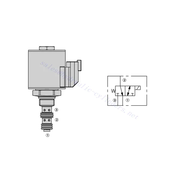
50SD58-30 Solenoïde richtingsventiel
Als één van de fabrikanten, de leveranciers en de exporteurs van van de hydraulische cilinders mechanische producten, bieden wij hydraulische cilinders en veel andere producten aan.
Neem contact met ons op voor meer informatie.
Mail:sales@hydraulic-cylinders.net
Fabrikant leverancier exporteur van hydraulische cilinders.
50SD58-30 Solenoïde richtingsventiel
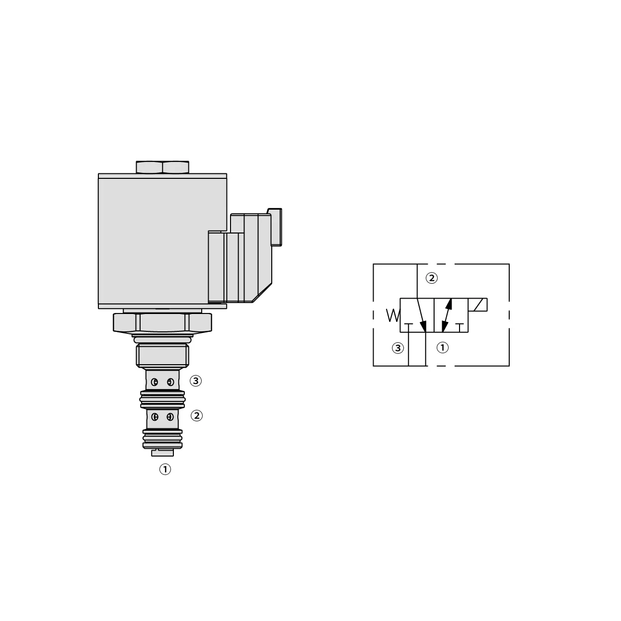
The 50SD58-30 solenoid directional valve is a versatile and high-performance component used in fluid control systems. Designed to provide precise control over fluid flow, this valve offers reliable operation and enhances the efficiency of various industrial applications.
The 30SD16-22 solenoid directional valve is essential for precise fluid control in industrial applications. Its robust construction, efficient performance, and versatility make it an ideal choice for many fluid control systems. Proper maintenance will ensure its optimal functionality and longevity. Invest in the 30SD16-22 solenoid directional valve to enhance fluid control operations and achieve exceptional results.
50SD58-30 Solenoid Directional Valve Characteristics:
- Durable Construction: The 50SD58-30 solenoid directional valve is built with high-quality materials, ensuring durability and resistance to wear, corrosion, and harsh operating conditions. Its robust construction makes it suitable for demanding industrial environments.
- Excellent Flow Control: This valve is engineered to deliver accurate and efficient fluid flow control. It offers exceptional repeatability and response times, enabling precise adjustments to meet specific application requirements.
- Versatile Configuration: The 50SD58-30 solenoid directional valve is available in various configurations, including inline, manifold, or subplate mounting options. This versatility allows for easy integration into different fluid control systems.
- Wide Range of Applications: This valve suits various applications across industries such as manufacturing, automation, process control, and more. It can control hydraulic, pneumatic, or other fluid-based systems.
50SD58-30 Solenoid Directional Valve Parameter:
| Nominale druk | 345 bar(5000 psi) | |
| Piekstroom | Zie prestatiegrafiek | |
| Vloeistof | Op mineralen gebaseerde of synthetische materialen met smerende eigenschappen | |
| Vloeistoftemperatuurbereik ℃ | -54 tot 107 ℃ (Polyurethaan afdichtingen) | |
| -40 tot 100 ℃ (Buna N-zeehonden) | ||
| -26 tot 204 ℃ (Fluorkoolstofafdichtingen) | ||
| Viscositeitsbereik | 7,4 tot 420 mm2/S | |
| Mate van verontreiniging | Het minimale vervuilingsniveau is ISO4406-niveau 18/16/13, en niveau 15/13/11 wordt aanbevolen om de levensduur te verlengen | |
| Interne lekkage | Port ③ (De-energized): ≤ 131 mL/min@345 bar | |
| Port ① (Energized): ≤ 279 mL/min@345 bar | ||
| Holte | VC08-3 | |
| Spoelbelastingsclassificatie | Continu van 85% tot 115% van nominale spanning | |
| Initiële spoelstroomopname bij 20℃ | E-spoel | 1,7 A bij 12 VDC; 0,85 A bij 24 VDC |
| D-spoel | 1,67 A bij 12 VDC; 0,83 A bij 24 VDC | |
| Minimale intrekspanning | 85% van nominaal bij 207 bar | |
50SD58-30 Solenoid Directional Valve Advantages:
• Spoel met continue belasting
• Cartridges zijn spanningsverwisselbaar
• Optionele waterdichte E-Coils met een IP69K-classificatie
• Efficiënte natte-ankerconstructie
• Geharde onderdelen voor een lange levensduur
Usage Method Of 50SD58-30 Solenoid Directional Valve:
- System Assessment: Understand the requirements of your fluid control system, including pressure, flow rate, and directional control needs. Ensure that the 50SD58-30 solenoid directional valve matches the specifications and is suitable for your application.
- Mounting and Connection: Select the appropriate mounting method based on your system layout and available space. Install the valve securely, ensuring proper alignment with the fluid lines. Connect the valve to the system using compatible fittings and connectors, providing tight and leak-free connections.
- Electrical Connection: Connect the valve’s solenoid to the appropriate power supply following the manufacturer’s instructions. Ensure correct wiring and adhere to safety guidelines during the electrical connection process.
- Testing and Adjustment: Gradually introduce fluid flow to the system and monitor the valve’s performance. Test different operating conditions, including pressure and flow variations, and adjust the valve settings to achieve the desired control and system functionality.
How To Replace Delta Shower Valve Cartridge?
Replacing a Delta shower valve cartridge is a common task that can help resolve issues such as leaks, temperature control problems, or water flow inconsistencies. Here’s a step-by-step guide on how to replace a Delta shower valve cartridge:
- Gather the necessary tools: Before you begin, make sure you have the following tools ready: adjustable wrench, Phillips screwdriver, needle-nose pliers, Allen wrench set, and a replacement cartridge specific to your Delta shower valve model.
- Turn off the water supply: Locate the main water shut-off valve for your home and turn it off to stop the water flow to the shower. If there is no dedicated shut-off valve for the shower, you may need to shut off the main water supply.
- Remove the handle: Depending on the Delta shower valve model, the handle removal method may vary. For single-handle valves, locate the set screw on the handle, usually located under a decorative cap or button. Use a Phillips screwdriver to remove the set screw, then pull the handle straight off. For two-handle valves, look for a small set screw on the base of each handle. Remove the set screws and then lift the handles off.
- Remove the trim sleeve and escutcheon plate: Next, remove the trim sleeve and escutcheon plate, which are usually located around the valve body. These components may be threaded or held in place with screws. Unscrew or remove any screws and gently pull or twist the sleeve and escutcheon plate to detach them from the wall.
- Disconnect the cartridge: Once you gain access to the cartridge, you may need to remove a retaining clip or nut that secures it in place. Use needle-nose pliers or an adjustable wrench to carefully loosen and remove the clip or nut. With the clip or nut removed, you can now pull the cartridge straight out of the valve body. If it’s stuck, you can use a cartridge puller tool for added leverage.
- Install the new cartridge: Take the replacement Delta shower valve cartridge and align it with the valve body, ensuring that any tabs or notches match up correctly. Gently push the cartridge into the valve body until it fits snugly.
- Reassemble the valve: Once the new cartridge is installed, reassemble the valve by following the steps in reverse order. Secure the cartridge with the retaining clip or nut, then reattach the trim sleeve and escutcheon plate. Make sure all components are tightened securely but avoid over-tightening.
- Test for leaks and functionality: Turn the water supply back on and test the shower. Check for any leaks around the valve and ensure that the hot and cold water controls are working correctly. If necessary, make any adjustments to the cartridge or connections to resolve any issues.
- Reinstall the handle: Finally, reattach the handle by aligning it with the cartridge stem and securing it with the set screw. Make sure the handle sits flush and operates smoothly.
Vermogen en capaciteit van de fabriek:
(1) Montage
We beschikken over een eersteklas, onafhankelijk R&D-platform voor assemblage. De productiewerkplaats voor hydraulische cilinders beschikt over vier semi-automatische hefcilinderassemblagelijnen en één automatische kantelcilinderassemblagelijn, met een geplande jaarlijkse productiecapaciteit van 1 miljoen stuks. De speciale cilinderwerkplaats is uitgerust met diverse specificaties van een semi-automatisch reinigingsassemblagesysteem met een geplande jaarlijkse productiecapaciteit van 200.000 stuks en is uitgerust met gerenommeerde CNC-bewerkingsapparatuur, een bewerkingscentrum, een zeer nauwkeurige cilinderbewerkingsapparatuur, een robotlasmachine, een automatische reinigingsmachine, een automatische cilinderassemblagemachine en een automatische verfproductielijn. De bestaande kritische apparatuur bestaat uit meer dan 300 sets. De optimale toewijzing en het efficiënte gebruik van apparatuur garanderen de nauwkeurigheidseisen van producten en voldoen aan de hoge kwaliteitseisen.


(2) Bewerking
De bewerkingsruimte is uitgerust met een op maat gemaakt schuin rails draaicentrum, bewerkingscentrum, hogesnelheids hoonmachine, lasrobot en andere bijbehorende apparatuur, die de bewerking van cilinderbuizen met een maximale binnendiameter van 400 mm en een maximale lengte van 6 meter aankan.

(3) Lassen

(4) Schilderen en coaten
Met kleine en middelgrote automatische cilindercoatinglijnen voor watergedragen verf, om automatisch laden en lossen door robots en automatisch spuiten te bereiken, is de ontwerpcapaciteit 4000 stuks per ploegendienst;
Ook beschikken wij over een semi-automatische verfproductielijn voor grote cilinders, aangedreven door een kabelrups, met een ontwerpcapaciteit van 60 dozen per ploeg.


(5) Testen
Wij beschikken over eersteklas inspectiefaciliteiten en testbanken om te garanderen dat de prestaties van de cilinder aan de eisen voldoen.

Wij zijn een van de beste fabrikanten van hydraulische cilinders. We bieden een compleet assortiment hydraulische cilinders. Ook leveren we bijbehorende onderdelen. landbouwversnellingsbakkenWe hebben onze producten wereldwijd geëxporteerd en een goede reputatie opgebouwd dankzij onze superieure productkwaliteit en aftersalesservice. We nodigen klanten in binnen- en buitenland uit om contact met ons op te nemen om zaken te doen, informatie uit te wisselen en werk met ons samen!
Toepassing hydraulische cilinder:
