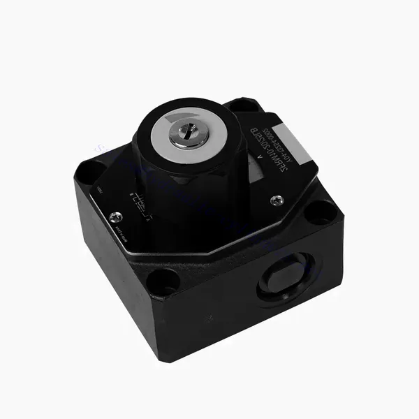
FRM Series Flow Control Hydraulic Valve
FRM Series Flow Control Hydraulic Valve
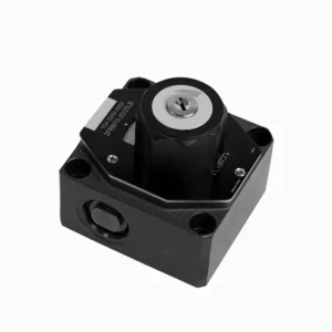
The FRM series flow control hydraulic valve is a cutting-edge hydraulic component designed to enhance the performance and control of hydraulic systems. With its advanced features and reliable functionality, this valve offers precise flow control and optimal efficiency.
The FRM series flow control hydraulic valve is a reliable and versatile solution for optimizing flow control in hydraulic systems. With its precise flow control capabilities, pressure and temperature stability, and durable construction, this valve offers enhanced performance and efficiency. Following the recommended usage methods and maintenance guidelines, operators can maximize the benefits of the FRM series flow control hydraulic valve, ensuring smooth operation and reliable flow control in their hydraulic applications. Upgrade your hydraulic system with this advanced valve and experience precision, efficiency, and productivity like never before.
FRM Series Flow Control Hydraulic Valve Key Characteristics:
- Flow Control Precision:
- The FRM series valve enables precise control over the flow rate of hydraulic fluids, allowing operators to fine-tune and regulate the speed of actuators.
- With its exceptional accuracy, this valve ensures consistent flow control, resulting in improved system performance and enhanced productivity.
- Veelzijdige toepassing:
- The FRM series valve is highly versatile and compatible with various hydraulic systems, including industrial machinery, construction equipment, and mobile applications.
- Its adaptability makes it an ideal choice for a wide range of hydraulic setups, providing reliable and efficient flow control.
- Druk- en temperatuurstabiliteit:
- This hydraulic valve is designed to maintain consistent flow control even under varying pressure and temperature conditions.
- It ensures stable performance and prevents flow fluctuations, safeguarding the integrity and reliability of the hydraulic system.
- Duurzame constructie:
- The FRM series valve is constructed with high-quality materials, ensuring durability and long-term reliability in demanding operating environments.
- Its robust design allows it to withstand high pressures, vibrations, and temperature extremes, providing a dependable solution for hydraulic applications.
FRM Series Flow Control Hydraulic Valve Parameter:
NG6
| Stroomregelklep | |||||||||||
| Max. werkdruk-poort A | bar | 315 | |||||||||
| Drukverschil ΔP voor vrije retourstroom B naar A | Zie karakteristieke curven | ||||||||||
| Minimaal drukverschil | bar | 6 tot 14 | |||||||||
| Drukstabiliteit tot P= 315 bar | % | ±2(Qmax) | |||||||||
| Stroom | Qmax | L/min | 0.2 | 0.6 | 1.5 | 3 | 6 | 10 | 16 | 25 | 32 |
| Qmin tot 100 bar | ml/min | 15 | 15 | 15 | 15 | 25 | 50 | 70 | 100 | 250 | |
| Qmin tot 315 bar | 25 | 25 | 25 | 25 | 25 | 50 | 70 | 100 | 250 | ||
| Vloeistof | Minerale olie, fosfaatester | ||||||||||
| Vloeistoftemperatuurbereik | ℃ | – 20 tot + 80 | |||||||||
| Viscositeitsbereik | mm2/s | 10 tot 800 | |||||||||
| Mate van verontreiniging | Maximaal toegestane mate van vloeistofverontreiniging: Klasse 9. NAS 1638 of 20/18/15, ISO4406 | ||||||||||
| Installatiepositie | Optioneel | ||||||||||
| Omstandigheden temperatuurbereik | ℃ | -20 tot +50 | |||||||||
| Gewicht | 2FRM6A…2FRM6B… | kg | ongeveer 1,3 | ||||||||
| 2FRM6SB… | kg | ongeveer 1,5 | |||||||||
| Gelijkrichter | |||||||||||
| Nominale stroom | bar | 320 | |||||||||
| Maximale werkdruk | bar | naar 210 | |||||||||
| Scheurdruk | bar | 0.7 | |||||||||
| Gewicht | kg | ongeveer 0,9 | |||||||||
NG5/10/16
| Stroomregelklep | ||||||||||||||||
| Max. werkdruk-poort A | bar | 315 | ||||||||||||||
| Drukverschil ΔP voor vrije retourstroom B naar A | Zie karakteristieke curven | |||||||||||||||
| Minimaal drukverschil | bar | 6 tot 14 | ||||||||||||||
| Vloeistof | Minerale olie, fosfaatester | |||||||||||||||
| Vloeistoftemperatuurbereik | ℃ | – 20 tot + 80 | ||||||||||||||
| Viscositeitsbereik | mm2/s | 10 tot 800 | ||||||||||||||
| Mate van verontreiniging | Maximaal toegestane mate van vloeistofverontreiniging: Klasse 9. NAS 1638 of 20/18/15, ISO4406 | |||||||||||||||
| Maat | mm | 5 | 10 | 16 | ||||||||||||
| Max. debiet | L/min | 0.2 | 0.6 | 1.2 | 3 | 6 | 10 | 15 | 10 | 16 | 25 | 50 | 60 | 100 | 160 | |
| Olieretourstroom B naar A | ml/min | 0.5 | 0.5 | 0.6 | 0.9 | 1.8 | 3.6 | 6.7 | 2 | 2.5 | 3.5 | 6 | 2.8 | 4.3 | 7.3 | |
| stromingsstabiel bereik (%Qmax)(-20-±80℃) | ±5 | ±3 | ±2 | ±2 | ||||||||||||
| ±2 (P=210 bar) | ±2 (P=350 bar) | |||||||||||||||
| Werkdruk | bar | 210 | 350 | |||||||||||||
| Minimale drukverlaging | bar | 3-5 | 6-8 | 3-7 | 5-12 | |||||||||||
| Gewicht | kg | 1.6 | 3.4 | 7.4 | ||||||||||||
| Gelijkrichter | ||||||||||||||||
| Vloeistof | Minerale olie, fosfaatester | |||||||||||||||
| Vloeistoftemperatuurbereik | -20 tot +80 | |||||||||||||||
| Viscositeitsbereik | 10 tot 800 | |||||||||||||||
| Mate van verontreiniging | Maximaal toegestane mate van vloeistofverontreiniging: Klasse 9. NAS 1638 of 20/18/15, ISO4406 | |||||||||||||||
| Maat | 5 | 10 | 16 | |||||||||||||
| Stroom | 15 | 50 | 160 | |||||||||||||
| Werkdruk | 210 | 315 | 315 | |||||||||||||
| Scheurdruk | 1 | 1.5 | 1.5 | |||||||||||||
| Gewicht | 0.6 | 3.2 | 9.3 | |||||||||||||
FRM Series Flow Control Hydraulic Valve Advantages:
• Montage op de bodemplaat, zie productcatalogus
• Drukcompensatie verplaatsingsbegrenzer, optioneel
• Optionele eenrichtingsklep
• Knop met schaalverdeling, optioneel afsluitbaar
Usage Method Of FRM Series Flow Control Hydraulic Valve:
- Systeemevaluatie:
- Begin by assessing the hydraulic system’s requirements, including flow rates, pressure ranges, and desired flow control parameters.
- Determine if the FRM series valve suits the specific application based on its flow control capabilities.
- Klepselectie:
- Select the appropriate variant of the FRM series valve based on the system parameters, desired flow rate, and compatibility with other system components.
- Houd rekening met factoren zoals maximale stroomcapaciteit, drukbereik en bedrijfsomstandigheden.
- Installatie:
- Volg de installatie-instructies van de fabrikant nauwkeurig op en zorg voor een goede uitlijning en veilige aansluitingen van de klep.
- Pay attention to the flow direction indicators, ensuring the correct positioning of the valve in the hydraulic system.
- Aanpassing van de stroomregeling:
- Once installed, adjust the flow control settings of the valve according to the desired flow rate and system requirements.
- Fine-tune the valve to achieve the desired speed and performance of hydraulic actuators, optimizing the overall system operation.
How Hydraulic Valves Work?
Hydraulic valves are crucial in controlling the flow and direction of hydraulic fluid within a hydraulic system. They are essential components that enable the precise operation of various hydraulic machinery and equipment. Here’s a simplified explanation of how hydraulic valves work:
- Basics of Hydraulic Systems:
Hydraulic systems use fluid, typically oil, to transmit power and control the movement of mechanical components. These systems consist of a hydraulic pump that pressurizes the liquid, a series of valves that control the flow and direction of the fluid, and hydraulic actuators (such as cylinders or motors) that convert the fluid energy into mechanical force or motion. - Valve Types:
There are various hydraulic valves, including directional control valves, pressure control valves, flow control valves, and check valves. Each valve type serves a specific purpose in regulating fluid flow, pressure, or direction. - Richtingsregelkleppen:
Directional control valves determine the path through which the hydraulic fluid flows. They have multiple positions (such as open, closed, or partially open) and multiple ports to direct the fluid to different sections of the hydraulic system. - Valve Components:
Hydraulic valves typically consist of a valve body, which contains internal passages and channels, and a movable valve element or spool that slides within the valve body. The spool has different lands or ports that align with the internal passages to control fluid flow. - Spool Movement:
The position of the spool within the valve body determines the flow path and, consequently, the direction of fluid flow. The spool can be actuated by various means, such as mechanical linkages, solenoids, or pilot pressure. - Drukregelkleppen:
Pressure control valves regulate the pressure of the hydraulic fluid within the system. They can maintain a specific pressure level by allowing excess fluid to return to the reservoir or blocking flow until a desired pressure is reached. - Stroomregelkleppen:
Flow control valves manage the rate of fluid flow within the hydraulic system. They can be used to control the speed of hydraulic actuators or to limit the flow rate to specific sections of the system. - Check Valves:
Check valves, or one-way valves, allow fluid flow in one direction and prevent backflow. They ensure that the fluid moves in the desired direction and avoid any undesired pressure drops or loss of hydraulic force. - Klepbediening:
Hydraulic valves can be manually operated, mechanically actuated, or controlled electronically. Levers or knobs directly handle manual valves, while mechanical and electronic actuators enable automated control of valve positions based on system requirements. - System Control:
By combining different types of hydraulic valves and controlling their positions or actuation, the hydraulic system’s overall function can be precisely regulated. This enables operators to control the movement, speed, force, and direction of hydraulic actuators, allowing for precise and efficient operation of hydraulic machinery.
Vermogen en capaciteit van de fabriek:
(1) Montage
We beschikken over een eersteklas, onafhankelijk R&D-platform voor assemblage. De productiewerkplaats voor hydraulische cilinders beschikt over vier semi-automatische hefcilinderassemblagelijnen en één automatische kantelcilinderassemblagelijn, met een geplande jaarlijkse productiecapaciteit van 1 miljoen stuks. De speciale cilinderwerkplaats is uitgerust met diverse specificaties van een semi-automatisch reinigingsassemblagesysteem met een geplande jaarlijkse productiecapaciteit van 200.000 stuks en is uitgerust met gerenommeerde CNC-bewerkingsapparatuur, een bewerkingscentrum, een zeer nauwkeurige cilinderbewerkingsapparatuur, een robotlasmachine, een automatische reinigingsmachine, een automatische cilinderassemblagemachine en een automatische verfproductielijn. De bestaande kritische apparatuur bestaat uit meer dan 300 sets. De optimale toewijzing en het efficiënte gebruik van apparatuur garanderen de nauwkeurigheidseisen van producten en voldoen aan de hoge kwaliteitseisen.


(2) Bewerking
De bewerkingsruimte is uitgerust met een op maat gemaakt schuin rails draaicentrum, bewerkingscentrum, hogesnelheids hoonmachine, lasrobot en andere bijbehorende apparatuur, die de bewerking van cilinderbuizen met een maximale binnendiameter van 400 mm en een maximale lengte van 6 meter aankan.

(3) Lassen

(4) Schilderen en coaten
Met kleine en middelgrote automatische cilindercoatinglijnen voor watergedragen verf, om automatisch laden en lossen door robots en automatisch spuiten te bereiken, is de ontwerpcapaciteit 4000 stuks per ploegendienst;
Ook beschikken wij over een semi-automatische verfproductielijn voor grote cilinders, aangedreven door een kabelrups, met een ontwerpcapaciteit van 60 dozen per ploeg.


(5) Testen
Wij beschikken over eersteklas inspectiefaciliteiten en testbanken om te garanderen dat de prestaties van de cilinder aan de eisen voldoen.

Wij zijn een van de beste fabrikanten van hydraulische cilinders. We bieden een compleet assortiment hydraulische cilinders. Ook leveren we bijbehorende onderdelen. landbouwversnellingsbakkenWe hebben onze producten wereldwijd geëxporteerd en een goede reputatie opgebouwd dankzij onze superieure productkwaliteit en aftersalesservice. We nodigen klanten in binnen- en buitenland uit om contact met ons op te nemen om zaken te doen, informatie uit te wisselen en werk met ons samen!


