

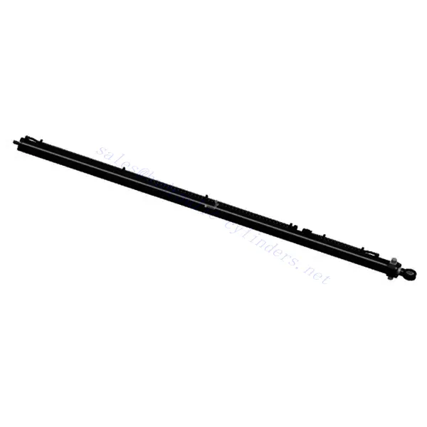
Drukcilinder voor roterend boren
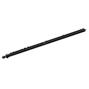

The rotary drilling pressurized cylinder is a high-performance hydraulic component specially designed to enhance efficiency and precision in rotary drilling operations. This cylinder plays a crucial role in controlling the vertical movement of the drilling mast, ensuring accurate positioning and optimized drilling performance.
The rotary drilling pressurized cylinder is indispensable for maximizing efficiency and precision in rotary drilling operations. With its superior construction, precise hydraulic control, adjustable stroke length, and enhanced stability, this cylinder empowers operators to position the drilling mast and optimize drilling performance accurately. By following proper usage methods and adhering to recommended maintenance practices, operators can ensure the longevity and reliability of the Rotary Drilling Pressurized Cylinder, leading to safe and efficient drilling operations. Choose this high-performance hydraulic component to elevate your drilling equipment and achieve exceptional drilling results.
Rotary Drilling Pressurized Cylinder Key Characteristics:
- Superior Construction:
- The rotary drilling pressurized cylinder is constructed with top-quality materials, guaranteeing durability and longevity.
- It is engineered to withstand the demanding conditions encountered in drilling operations, including heavy loads, vibrations, and extreme environments.
- Precise Hydraulic Control:
- This cylinder operates through a hydraulic control system, utilizing pressurized hydraulic fluid to control the vertical movement of the drilling mast.
- The precise hydraulic control ensures accurate and responsive movement, allowing for precise positioning and control during drilling operations.
- Adjustable Stroke Length:
- The rotary drilling pressurized cylinder offers an adjustable stroke length, providing flexibility to accommodate various drilling requirements and ground conditions.
- This adjustability allows operators to achieve optimal drilling performance and adapt to different project specifications.
- Enhanced Stability and Safety:
- The cylinder’s design emphasizes stability and safety during drilling operations.
- It effectively minimizes vibrations and ensures smooth movements, enhancing the overall stability of the drilling mast.
Rotary Drilling Pressurized Cylinder Parameter:
| Productnaam | Drukcilinder voor roterend boren |
| Functies: | Control the lifting and lowering of the power head |
| Boordiameter: | 125mm~210mm |
| Staafdiameter: | 90mm~150mm Stroke≤8500mm |
| Druk: | tot 35 MPa |
| Pressurized Cylinder Applications: | Roterend boren |
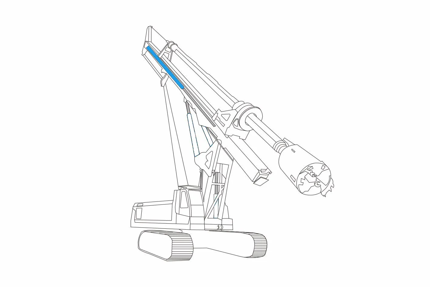
Rotary Drilling Pressurized Cylinder Identification Diagram:

Usage Method Of Rotary Drilling Pressurized Cylinder:
- Maak kennis met de operationele controles en veiligheidsrichtlijnen:
- Before operating the rotary drilling equipment, it is crucial to become familiar with the equipment manufacturer’s operational controls and safety guidelines.
- Strictly adhere to all safety procedures and precautions to ensure safe and efficient drilling operations.
- Adjusting the Stroke Length:
- Use the control mechanism, such as a control panel or joystick, to activate the rotary drilling pressurized cylinder.
- Adjust the stroke length according to the specific drilling requirements and ground conditions.
- The cylinder will translate the pressurized hydraulic fluid into the required force for precise positioning of the drilling mast.
- Monitoring and Adjusting Drilling Mast Position:
- Continuously monitor the position of the drilling mast during operation.
- Make necessary adjustments to ensure accurate drilling and maintain the desired drilling height.
Welke wet van de hydrauliek gebruikt het remsysteem?
The brake system in vehicles commonly utilizes Pascal’s law of hydraulics. Pascal’s law states that when pressure is applied to a fluid in an enclosed system, the pressure is transmitted equally in all directions. In a vehicle’s brake system, this law allows for the transfer of force from the driver’s foot pressing the brake pedal to the brake calipers at each wheel.
Here’s a simplified explanation of how the brake system uses Pascal’s law:
- Brake Pedal:
When the driver presses the brake pedal, it applies force to a piston in the master cylinder. - Hoofdremcilinder:
The master cylinder contains hydraulic fluid and houses the piston. As the driver pushes the brake pedal, the piston compresses the fluid and increases the pressure. - Hydraulische leidingen:
The increased pressure is transmitted through the hydraulic lines, which connect the master cylinder to the brake calipers or wheel cylinders at each wheel. - Remklauwen/Wielcilinders:
The brake calipers (in disc brakes) or wheel cylinders (in drum brakes) contain pistons that are acted upon by the hydraulic pressure. The pressure exerted by the hydraulic fluid causes the pistons to move, applying force to the brake pads or brake shoes. - Brake Pads/Shoes:
The brake pads (in disc brakes) or brake shoes (in drum brakes) are pressed against the rotating brake discs or drums, creating friction. This friction slows down or stops the rotation of the wheels, thereby decelerating the vehicle.
Vermogen en capaciteit van de fabriek:
(1) Montage
We beschikken over een eersteklas, onafhankelijk R&D-platform voor assemblage. De productiewerkplaats voor hydraulische cilinders beschikt over vier semi-automatische hefcilinderassemblagelijnen en één automatische kantelcilinderassemblagelijn, met een geplande jaarlijkse productiecapaciteit van 1 miljoen stuks. De speciale cilinderwerkplaats is uitgerust met diverse specificaties van een semi-automatisch reinigingsassemblagesysteem met een geplande jaarlijkse productiecapaciteit van 200.000 stuks en is uitgerust met gerenommeerde CNC-bewerkingsapparatuur, een bewerkingscentrum, een zeer nauwkeurige cilinderbewerkingsapparatuur, een robotlasmachine, een automatische reinigingsmachine, een automatische cilinderassemblagemachine en een automatische verfproductielijn. De bestaande kritische apparatuur bestaat uit meer dan 300 sets. De optimale toewijzing en het efficiënte gebruik van apparatuur garanderen de nauwkeurigheidseisen van producten en voldoen aan de hoge kwaliteitseisen.


(2) Bewerking
De bewerkingsruimte is uitgerust met een op maat gemaakt schuin rails draaicentrum, bewerkingscentrum, hogesnelheids hoonmachine, lasrobot en andere bijbehorende apparatuur, die de bewerking van cilinderbuizen met een maximale binnendiameter van 400 mm en een maximale lengte van 6 meter aankan.


(3) Lassen


(4) Schilderen en coaten
Met kleine en middelgrote automatische cilindercoatinglijnen voor watergedragen verf, om automatisch laden en lossen door robots en automatisch spuiten te bereiken, is de ontwerpcapaciteit 4000 stuks per ploegendienst;
Ook beschikken wij over een semi-automatische verfproductielijn voor grote cilinders, aangedreven door een kabelrups, met een ontwerpcapaciteit van 60 dozen per ploeg.


(5) Testen
Wij beschikken over eersteklas inspectiefaciliteiten en testbanken om te garanderen dat de prestaties van de cilinder aan de eisen voldoen.


Wij zijn een van de beste fabrikanten van hydraulische cilinders. We bieden een compleet assortiment hydraulische cilinders. Ook leveren we bijbehorende onderdelen. landbouwversnellingsbakkenWe hebben onze producten wereldwijd geëxporteerd en een goede reputatie opgebouwd dankzij onze superieure productkwaliteit en aftersalesservice. We nodigen klanten in binnen- en buitenland uit om contact met ons op te nemen om zaken te doen, informatie uit te wisselen en werk met ons samen!