
WMR-serie richtingshydraulische klep met mechanische, handmatige bediening
Als één van de fabrikanten, de leveranciers en de exporteurs van van de hydraulische cilinders mechanische producten, bieden wij hydraulische cilinders en veel andere producten aan.
Neem contact met ons op voor meer informatie.
Mail:sales@hydraulic-cylinders.net
Fabrikant leverancier exporteur van hydraulische cilinders.
WMR-serie richtingshydraulische klep met mechanische, handmatige bediening
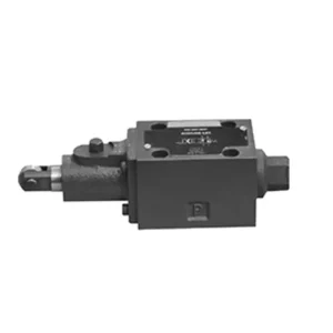
The WMR series directional hydraulic valve with mechanical, manual operation is a cutting-edge solution designed to deliver precise control in hydraulic systems. This valve offers enhanced efficiency and flexibility with its advanced features and robust construction.
The WMR series directional hydraulic valve with mechanical, manual operation is a reliable and versatile solution for hydraulic systems. Its automatic and manual operation and precise directional control offer enhanced flexibility and control for various applications. Following the recommended usage methods and adhering to regular maintenance practices, the WMR series valve will continue providing efficient and reliable operation. Upgrade your hydraulic system with the WMR series directional hydraulic valve and experience the benefits of enhanced control and versatility.
WMR Series Directional Hydraulic Valve With Mechanical, Manual Operation Key Characteristics:
- Mechanisch, handmatige bediening:
- The WMR series valve features a mechanical, manual operation, allowing operators to control the valve position manually.
- Dit biedt flexibiliteit en controle in toepassingen waarbij handmatige bediening gewenst of vereist is.
- Richtingscontrole:
- This hydraulic valve enables precise directional fluid flow control within the hydraulic system.
- Hierdoor kunnen operators het gewenste stroompad selecteren, wat zorgt voor een efficiënte en betrouwbare werking.
- Duurzame constructie:
- The WMR series valve is constructed with high-quality materials, ensuring durability and longevity.
- Its robust design can withstand demanding operating conditions, providing reliable performance.
- Wide Range of Applications:
- The WMR series valve suits various industries and applications, including manufacturing, construction, agriculture, etc.
- It can be utilized in hydraulic systems that require accurate and efficient fluid control.
WMR Series Directional Hydraulic Valve With Mechanical, Manual Operation Parameter:
NG6
| Installatiepositie | Optioneel | ||
| Vloeistoftemperatuurbereik | ℃ | -30 tot +80 (NBR-afdichtingen) | |
| -20 tot +80 (FKM-afdichtingen) | |||
| Poort Max. werkdruk | Haven ABP | bar | 315 |
| Poort T | bar | 60 | |
| Max. debiet | L/min | 60 | |
| Doorstromingsdoorsnede (schakelende neutrale positie) | Q-type | mm2 | For symbol Q, 6% of the nominal cross-section |
| W-type | mm2 | For symbol W, 3% of the nominal cross-section | |
| Vloeistof | Minerale olie; Fosfaatester | ||
| Viscositeitsbereik | mm2/S | 2,8 tot 500 | |
| Mate van verontreiniging | Maximaal toegestane mate van vloeistofverontreiniging: Klasse 9. NAS 1638 of 20/18/15, ISO4406 | ||
| Gewicht | kg | 1.4 | |
NG10
| Installatiepositie | Optioneel | ||
| Vloeistoftemperatuurbereik | ℃ | -30 tot +80 (NBR-afdichtingen) | |
| -20 tot +80 (FKM-afdichtingen) | |||
| Poort Max. werkdruk | Haven ABP | bar | 315 |
| Poort T | bar | 60 | |
| Max. debiet | L/min | 120 | |
| Doorstromingsdoorsnede (schakelende neutrale positie) | V-type | mm2 | 11(A/B → T);10.3(P → A/B) |
| W-type | mm2 | 2,5(A/B → T) | |
| Q-type | mm2 | 5,5(A/B → T) | |
| Vloeistof | Minerale olie; Fosfaatester | ||
| Viscositeitsbereik | mm2/S | 2,8 tot 500 | |
| Mate van verontreiniging | Maximaal toegestane mate van vloeistofverontreiniging: Klasse 9. NAS 1638 of 20/18/15, ISO4406 | ||
| Gewicht | kg | 4 | |
WMR Series Directional Hydraulic Valve With Mechanical, Manual Operation Advantages:
• Direct werkende richtingsschuifklep direct werkende richtingsschuifklep
• Scroll wheel can rotate 90°
• Nineteen standard slide valve functions
Usage Method Of WMR Series Directional Hydraulic Valve With Mechanical, Manual Operation:
- Systeemintegratie:
- Identify the appropriate location for the WMR series valve within the hydraulic system, considering the desired flow direction and control requirements.
- Zorg voor compatibiliteit met de druk- en stroomspecificaties van het systeem.
- Bevestig de klep stevig met behulp van geschikte beugels of montageaccessoires.
- Vloeistofverbindingen:
- Kies compatibele hydraulische koppelingen en slangen voor veilige en lekvrije verbindingen.
- Volg de instructies van de fabrikant voor de juiste aanhaalmomenten tijdens het installatieproces.
- Gebruik geschikte schroefdraadafdichtingsmiddelen of tape om een betrouwbare afdichting te garanderen.
- Handmatige bediening:
- Maak uzelf vertrouwd met het handmatige bedieningsmechanisme van de klep, inclusief de hendel of knop waarmee u de klepstand regelt.
- Ensure the operator understands the correct procedure for manually adjusting the valve position.
- Systeemkalibratie:
- Kalibreer de kleppositie en -beweging volgens de gewenste stroomrichting en regelvereisten.
- Stel de klep handmatig in om het gewenste stromingspad te verkrijgen en een goede werking te garanderen.
How To Adjust Hydraulic Valve Lifters?
Adjusting hydraulic valve lifters is a crucial maintenance task to ensure proper engine performance and prevent issues like valve train noise and reduced power. Here’s a step-by-step guide on how to adjust hydraulic valve lifters:
- Prepare the Engine:
- Before starting the adjustment process, make sure the engine is turned off and cool to the touch.
- Remove any components necessary to access the valve covers, such as the air cleaner assembly or spark plug wires.
- Identify the Correct Valve Adjustment Sequence:
- Consult the engine manufacturer’s specifications or service manual to determine the correct valve adjustment sequence for your specific engine.
- Some engines have a firing order that dictates the sequence, while others have specific instructions based on cylinder numbering.
- Locate the Top Dead Center (TDC) Position:
- Rotate the engine’s crankshaft in the normal direction of rotation until the number one piston reaches the top dead center (TDC) position on its compression stroke.
- Use a timing mark on the harmonic balancer or flywheel and a timing pointer to determine the TDC position accurately.
- Adjusting Valve Lifters:
- Start with the first cylinder in the valve adjustment sequence.
- Remove the valve cover to access the rocker arms and valve lifters.
- Loosen the lock nut on the rocker’s arm using an appropriate wrench or socket.
- Turn the adjusting screw or stud on the rocker’s arm clockwise to decrease the valve clearance or counterclockwise to increase it.
- Check the engine manufacturer’s specifications for the recommended valve clearance. Use a feeler gauge to measure the clearance between the rocker arm and the valve stem.
- Adjust the valve lifter until the proper clearance is achieved. You should feel slight resistance but still be able to move the feeler gauge back and forth.
- Hold the adjusting screw or stud in place and tighten the lock nut securely.
- Herhaal het proces:
- Move to the next cylinder in the valve adjustment sequence and repeat steps 4 and 5 until all the valve lifters have been adjusted.
- Reinstall Valve Covers:
- Once you’ve completed the valve adjustment on all cylinders, reinstall the valve covers and ensure they are properly sealed to prevent oil leaks.
- Double-Check:
- After adjusting the valve lifters, it’s advisable to go through the entire valve adjustment sequence once more to confirm that all clearances are within the specified range.
Vermogen en capaciteit van de fabriek:
(1) Montage
We beschikken over een eersteklas, onafhankelijk R&D-platform voor assemblage. De productiewerkplaats voor hydraulische cilinders beschikt over vier semi-automatische hefcilinderassemblagelijnen en één automatische kantelcilinderassemblagelijn, met een geplande jaarlijkse productiecapaciteit van 1 miljoen stuks. De speciale cilinderwerkplaats is uitgerust met diverse specificaties van een semi-automatisch reinigingsassemblagesysteem met een geplande jaarlijkse productiecapaciteit van 200.000 stuks en is uitgerust met gerenommeerde CNC-bewerkingsapparatuur, een bewerkingscentrum, een zeer nauwkeurige cilinderbewerkingsapparatuur, een robotlasmachine, een automatische reinigingsmachine, een automatische cilinderassemblagemachine en een automatische verfproductielijn. De bestaande kritische apparatuur bestaat uit meer dan 300 sets. De optimale toewijzing en het efficiënte gebruik van apparatuur garanderen de nauwkeurigheidseisen van producten en voldoen aan de hoge kwaliteitseisen.


(2) Bewerking
De bewerkingsruimte is uitgerust met een op maat gemaakt schuin rails draaicentrum, bewerkingscentrum, hogesnelheids hoonmachine, lasrobot en andere bijbehorende apparatuur, die de bewerking van cilinderbuizen met een maximale binnendiameter van 400 mm en een maximale lengte van 6 meter aankan.

(3) Lassen

(4) Schilderen en coaten
Met kleine en middelgrote automatische cilindercoatinglijnen voor watergedragen verf, om automatisch laden en lossen door robots en automatisch spuiten te bereiken, is de ontwerpcapaciteit 4000 stuks per ploegendienst;
Ook beschikken wij over een semi-automatische verfproductielijn voor grote cilinders, aangedreven door een kabelrups, met een ontwerpcapaciteit van 60 dozen per ploeg.


(5) Testen
Wij beschikken over eersteklas inspectiefaciliteiten en testbanken om te garanderen dat de prestaties van de cilinder aan de eisen voldoen.

Wij zijn een van de beste fabrikanten van hydraulische cilinders. We bieden een compleet assortiment hydraulische cilinders. Ook leveren we bijbehorende onderdelen. landbouwversnellingsbakkenWe hebben onze producten wereldwijd geëxporteerd en een goede reputatie opgebouwd dankzij onze superieure productkwaliteit en aftersalesservice. We nodigen klanten in binnen- en buitenland uit om contact met ons op te nemen om zaken te doen, informatie uit te wisselen en werk met ons samen!
Toepassing hydraulische cilinder:
