ZDR Series Direct Operated Pressure Reducing Hydraulic Valve
Als één van de fabrikanten, de leveranciers en de exporteurs van van de hydraulische cilinders mechanische producten, bieden wij hydraulische cilinders en veel andere producten aan.
Neem contact met ons op voor meer informatie.
Mail:sales@hydraulic-cylinders.net
Fabrikant leverancier exporteur van hydraulische cilinders.
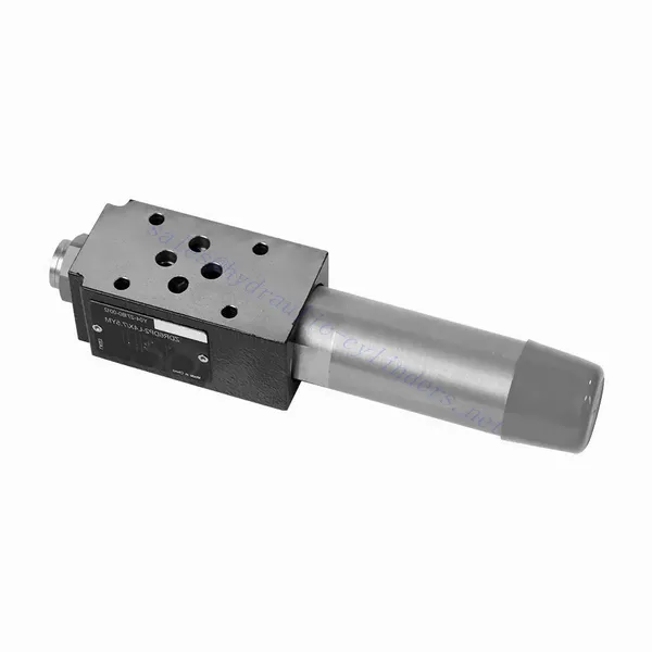
ZDR Series Direct Operated Pressure Reducing Hydraulic Valve
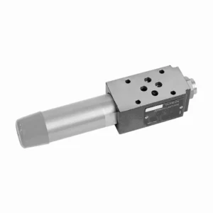
The ZDR series direct-operated pressure-reducing hydraulic valve is a highly efficient and reliable component that provides accurate pressure control in hydraulic systems. With its direct-operated design and exceptional performance, this valve ensures precise pressure reduction to meet specific system requirements.
The ZDR series direct-operated pressure-reducing hydraulic valve is a high-performance solution for precise pressure control in hydraulic systems. With its direct-operated design, accurate pressure control, wide pressure range, and high flow capacity, this valve ensures efficient and reliable pressure reduction while protecting system components. By following the recommended usage methods and maintenance practices, the ZDR series valve delivers reliable performance, extending the lifespan of hydraulic systems. Upgrade your hydraulic system with the ZDR series direct-operated pressure-reducing hydraulic valve and experience optimal pressure control for enhanced system efficiency and productivity.
ZDR Series Direct Operated Pressure Reducing Hydraulic Valve Key Characteristics:
- Direct-bediend ontwerp:
- The ZDR series valve features a direct-operated design, which enables it to provide precise pressure control without the need for external pilot circuits.
- This design simplifies installation and reduces complexity in hydraulic systems.
- Accurate Pressure Control:
- This valve offers exceptional accuracy in pressure control, allowing hydraulic systems to maintain the desired pressure range with high reliability.
- It ensures stable operation and protects sensitive system components from excessive pressure.
- Breed drukbereik:
- The ZDR series valve is available in various pressure ranges, making it suitable for diverse hydraulic applications.
- The flexibility in pressure range allows customization to match specific system requirements and optimize performance.
- Hoge stroomcapaciteit:
- This valve exhibits excellent flow capacity, enabling it to handle high flow rates while maintaining precise pressure control.
- It ensures efficient fluid regulation and uninterrupted system operation, even in demanding applications.
ZDR Series Direct Operated Pressure Reducing Hydraulic Valve Parameter:
| Specificaties | NG10 | NG16 | ||
| Vloeistof | Minerale olie geschikt voor NBR- en FKM-afdichting | |||
| Fosfaatester voor FKM-afdichting | ||||
| Vloeistoftemperatuurbereik | ℃ | -30 to +80 (NBR seals) | ||
| -20 tot +80 (FKM-afdichtingen) | ||||
| Viscositeitsbereik | mm2/S | 10 tot 800 | ||
| Mate van verontreiniging | Maximaal toegestane mate van vloeistofverontreiniging: Klasse 9. NAS 1638 of 20/18/15, ISO4406 | |||
| Nominal pressure | bar | 315 | ||
| Maximale werkdruk | Port P | bar | 315 | |
| Maximale werkdruk | Port A | bar | 315 | 250 |
| Maximale werkdruk | Haven Y | bar | Gescheiden en onder nul druk naar de tank | |
| Druk instellen | Min. | bar | Dependent on the flow (see curves) | |
| Max. | bar | 50; 100; 200; 315 | 50; 100; 200; 250 | |
| Max. debiet | L/min | 120 | 220 | |
| Gewicht | kg | ongeveer 6,5 | about 8.8 | |
ZDR Series Direct Operated Pressure Reducing Hydraulic Valve Advantages:
• Sandwich-achtige structuur
• Installatievlak volgens DIN 24340 A en ISO 4401
• Vier drukbereiken
• Twee verstelmogelijkheden: knop, verstelschroef met beschermkap
• Met manometerinterface
• Optioneel eenrichtingsventiel
Usage Method Of ZDR Series Direct Operated Pressure Reducing Hydraulic Valve:
- Systeemanalyse:
- Conduct a thorough hydraulic system analysis to determine the specific pressure control requirements.
- Houd rekening met de maximale werkdruk, het gewenste drukbereik en de debieten.
- Klepselectie:
- Select the appropriate ZDR series valve variant based on the system’s pressure control specifications.
- Houd rekening met de drukclassificatie, de stroomcapaciteit en de compatibiliteit met andere systeemcomponenten.
- Installatie:
- Follow the manufacturer’s instructions to correctly install the ZDR series direct-operated pressure-reducing valve in the hydraulic system.
- Zorg voor een goede uitlijning en veilige verbindingen om lekkages te voorkomen en de prestaties te optimaliseren.
- Kalibratie:
- Calibrate the valve to set the desired downstream pressure.
- Gebruik drukmeters of andere meetinstrumenten om de klep nauwkeurig af te stellen voor een optimale drukregeling.
How Does A Hydraulic Selector Valve Work?
A hydraulic selector valve, also known as a hydraulic diverter valve or hydraulic control valve, is a device used to direct the flow of hydraulic fluid in a hydraulic system. It allows the operator to control the path of fluid flow by selecting different hydraulic circuits or components to operate. Here’s a breakdown of how a hydraulic selector valve works:
- Klepconstructie:
- A hydraulic selector valve consists of a body with multiple ports and internal passages.
- It typically has an actuating mechanism, such as a lever or a solenoid, to control the movement of the valve spool or poppet.
- Port Configuration:
- A selector valve has multiple ports, usually labeled as A, B, and C, or sometimes referred to as P, T, and A/B/C.
- Port P (Pressure) connects to the hydraulic pump or the high-pressure side of the system.
- Port T (Tank) connects to the hydraulic reservoir or the low-pressure side of the system.
- Ports A, B, and C are the output ports that connect to different hydraulic circuits or components.
- Klepposities:
- The selector valve has different positions that determine the flow path of the hydraulic fluid.
- Common positions include “A,” “B,” “C,” “AB,” “AC,” and “BC,” depending on the specific valve design.
- Vloeistofstroomregeling:
- When the valve is in the neutral or default position, typically labeled “N,” the fluid flow is blocked, and no flow occurs between any of the ports.
- When the operator actuates the valve by moving the lever or energizing the solenoid, the valve spool or poppet shifts to a different position, enabling fluid flow.
- Flow Path Selection:
- By moving the actuating mechanism, the operator can select the desired flow path.
- For example, when the valve is in position “A,” fluid flows from port P to port A, allowing the hydraulic circuit or component connected to port A to operate.
- Multiple Flow Paths:
- Depending on the specific valve design, a hydraulic selector valve can provide multiple flow paths.
- For instance, in position “AB,” fluid can flow from port P to both ports A and B simultaneously, allowing operation of two separate hydraulic circuits or components.
- Bediening en bediening:
- The actuating mechanism of the selector valve can be manual, where the operator physically moves a lever or knob, or it can be electric or pneumatic, using solenoids or other control devices.
- Electrically controlled selector valves can be integrated into automated systems or controlled remotely.
- System Flexibility:
- Hydraulic selector valves provide flexibility in system design and operation.
- They allow the operator to switch between different hydraulic circuits or components, facilitating tasks such as equipment positioning, attachment control, or switching between different implements.
Vermogen en capaciteit van de fabriek:
(1) Montage
We beschikken over een eersteklas, onafhankelijk R&D-platform voor assemblage. De productiewerkplaats voor hydraulische cilinders beschikt over vier semi-automatische hefcilinderassemblagelijnen en één automatische kantelcilinderassemblagelijn, met een geplande jaarlijkse productiecapaciteit van 1 miljoen stuks. De speciale cilinderwerkplaats is uitgerust met diverse specificaties van een semi-automatisch reinigingsassemblagesysteem met een geplande jaarlijkse productiecapaciteit van 200.000 stuks en is uitgerust met gerenommeerde CNC-bewerkingsapparatuur, een bewerkingscentrum, een zeer nauwkeurige cilinderbewerkingsapparatuur, een robotlasmachine, een automatische reinigingsmachine, een automatische cilinderassemblagemachine en een automatische verfproductielijn. De bestaande kritische apparatuur bestaat uit meer dan 300 sets. De optimale toewijzing en het efficiënte gebruik van apparatuur garanderen de nauwkeurigheidseisen van producten en voldoen aan de hoge kwaliteitseisen.


(2) Bewerking
De bewerkingsruimte is uitgerust met een op maat gemaakt schuin rails draaicentrum, bewerkingscentrum, hogesnelheids hoonmachine, lasrobot en andere bijbehorende apparatuur, die de bewerking van cilinderbuizen met een maximale binnendiameter van 400 mm en een maximale lengte van 6 meter aankan.

(3) Lassen

(4) Schilderen en coaten
Met kleine en middelgrote automatische cilindercoatinglijnen voor watergedragen verf, om automatisch laden en lossen door robots en automatisch spuiten te bereiken, is de ontwerpcapaciteit 4000 stuks per ploegendienst;
Ook beschikken wij over een semi-automatische verfproductielijn voor grote cilinders, aangedreven door een kabelrups, met een ontwerpcapaciteit van 60 dozen per ploeg.


(5) Testen
Wij beschikken over eersteklas inspectiefaciliteiten en testbanken om te garanderen dat de prestaties van de cilinder aan de eisen voldoen.

Wij zijn een van de beste fabrikanten van hydraulische cilinders. We bieden een compleet assortiment hydraulische cilinders. Ook leveren we bijbehorende onderdelen. landbouwversnellingsbakkenWe hebben onze producten wereldwijd geëxporteerd en een goede reputatie opgebouwd dankzij onze superieure productkwaliteit en aftersalesservice. We nodigen klanten in binnen- en buitenland uit om contact met ons op te nemen om zaken te doen, informatie uit te wisselen en werk met ons samen!
Toepassing hydraulische cilinder:
