Zawór hydrauliczny kierunkowy serii WMM z obsługą mechaniczną i ręczną
Zawór hydrauliczny kierunkowy serii WMM z obsługą mechaniczną i ręczną
Zawór hydrauliczny kierunkowy serii WMM z mechaniczną, ręczną obsługą to wszechstronne i niezawodne rozwiązanie przeznaczone do precyzyjnego sterowania układami hydraulicznymi. Ten zawór hydrauliczny oferuje zwiększoną wydajność i elastyczność dzięki zaawansowanym funkcjom i solidnej konstrukcji.
Zawór hydrauliczny kierunkowy serii WMM z mechaniczną, ręczną obsługą to niezawodne i wszechstronne rozwiązanie dla układów hydraulicznych. Automatyczna, ręczna obsługa i precyzyjne sterowanie kierunkowe zapewniają większą elastyczność i kontrolę w różnych zastosowaniach. Przestrzeganie zalecanych metod użytkowania i regularnych praktyk konserwacyjnych zapewni wydajną i niezawodną pracę zaworu hydraulicznego serii WMM. Zmodernizuj swój układ hydrauliczny, wybierając zawór kierunkowy serii WMM i doświadcz korzyści płynących z lepszej kontroli i wszechstronności.
Główne cechy rozdzielacza hydraulicznego kierunkowego serii WMM z obsługą mechaniczną i ręczną:
- Mechaniczna, obsługa ręczna:
- Zawór hydrauliczny serii WMM charakteryzuje się mechaniczną, ręczną obsługą, umożliwiającą operatorom ręczną kontrolę położenia zaworu.
- Zapewnia to elastyczność i kontrolę w zastosowaniach, w których wymagana lub pożądana jest obsługa ręczna.
- Kontrola kierunkowa:
- Ten zawór hydrauliczny umożliwia precyzyjną kontrolę kierunku przepływu cieczy w układzie hydraulicznym.
- Umożliwia operatorom wybór pożądanej ścieżki przepływu, zapewniając wydajną i niezawodną pracę.
- Trwała konstrukcja:
- Zawory hydrauliczne serii WMM wykonane są z materiałów najwyższej jakości, co zapewnia trwałość i długowieczność.
- Jego solidna konstrukcja wytrzymuje trudne warunki pracy i gwarantuje niezawodną wydajność.
- Kompaktowy rozmiar:
- Kompaktowe rozmiary zaworu pozwalają na łatwą integrację z systemami hydraulicznymi o ograniczonej przestrzeni.
- Idealnie nadaje się do zastosowań, w których przestrzeń jest ograniczona, bez kompromisów w zakresie wydajności.
Zawór hydrauliczny kierunkowy serii WMM z obsługą mechaniczną i ręczną Parametry:
NG6
| Zakres temperatur cieczy | ℃ | -30 do +80 (uszczelki NBR) | |
| -20 do +80 (uszczelki FKM) | |||
| Maksymalne ciśnienie robocze portu | Port ABP | bar | 315 |
| Port T | bar | 160 | |
| Maksymalny przepływ | l/min | 60 | |
| Flowarea (przełączanie pozycji neutralnej) | Typ Q | mm2 | Dla symbolu Q, 6% przekroju nominalnego |
| Typ W | mm2 | Dla symbolu W, 3% przekroju nominalnego | |
| Płyn | Olej mineralny; ester fosforanowy | ||
| Zakres lepkości | mm2/S | 2,8 do 500 | |
| Stopień skażenia | Maksymalny dopuszczalny stopień zanieczyszczenia płynem: Klasa 9. NAS 1638 lub 20/18/15, ISO4406 | ||
| Waga | kg | 1.6 | |
NG10
| Zakres temperatur cieczy | ℃ | -30 do +80 (uszczelki NBR) | |
| -20 do +80 (uszczelki FKM) | |||
| Maksymalne ciśnienie robocze portu | Port ABP | bar | 315 |
| Port T | bar | 160 | |
| Maksymalny przepływ | l/min | 120 | |
| Przekrój przepływu (przełączanie położenia neutralnego) | Typ V | mm2 | 11(A/B → T);10.3(P → A/B) |
| Typ W | mm2 | 2,5(A/B → T) | |
| Typ Q | mm2 | 5.5(A/B → T) | |
| Płyn | Olej mineralny; ester fosforanowy | ||
| Zakres lepkości | mm2/S | 2,8 do 500 | |
| Stopień skażenia | Maksymalny dopuszczalny stopień zanieczyszczenia płynem: Klasa 9. NAS 1638 lub 20/18/15, ISO4406 | ||
| Waga | kg | 4.4 | |
NG16-32
| NS | 16 | 25 | 32 |
| Waga | około 8 | około 12,2 | około 49 |
| Siła zadziałania z blokadą N | około 75 | około 105 | około 170 |
| z powrotem sprężynowym N | |||
| Kąt zadziałania względem położenia neutralnego | 2*26° | 2*32° | 2*30° |
| Maksymalne ciśnienie robocze Port A, B, P bar | 315 | ||
| Port T bar | 250 | ||
| Płyn | Olej mineralny odpowiedni do uszczelnień NBR i FKM | ||
| Ester fosforanowy – do uszczelnień FKM | |||
| Zakres temperatur cieczy | -30 do +80 (uszczelnienie NBR) | ||
| -20 do +80 (uszczelnienie FKM) | |||
| Zakres lepkości mm2/S | 2,8 do 380 | ||
| Stopień skażenia | Maksymalny dopuszczalny stopień zanieczyszczenia płynem: Klasa 9. NAS 1638 lub 20/18/15, ISO4406 | ||
Zalety zaworów hydraulicznych kierunkowych serii WMM z obsługą mechaniczną i ręczną:
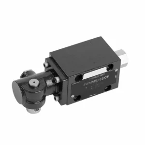
• Zawór suwakowy kierunkowy bezpośredniego działania Zawór suwakowy kierunkowy bezpośredniego działania
• Montaż na płycie pomocniczej
• Sterowanie uchwytem
• Montaż powierzchniowy zgodnie z normami DIN 24340 A, ISO 4401
Sposób użycia zaworu hydraulicznego kierunkowego serii WMM z obsługą mechaniczną i ręczną:
- Integracja systemów:
- Określ odpowiednie miejsce dla zaworu hydraulicznego serii WMM w układzie hydraulicznym, biorąc pod uwagę pożądany kierunek przepływu i wymagania dotyczące sterowania.
- Zapewnij zgodność ze specyfikacjami ciśnienia i przepływu w systemie.
- Zamontuj zawór w sposób bezpieczny, używając odpowiednich wsporników lub akcesoriów montażowych.
- Połączenia płynne:
- Wybierz kompatybilne złączki hydrauliczne i węże, aby zapewnić bezpieczne i szczelne połączenia.
- Podczas instalacji należy przestrzegać instrukcji producenta dotyczących właściwych wartości momentu obrotowego.
- Aby zapewnić niezawodne uszczelnienie, należy stosować odpowiednie uszczelniacze gwintów lub taśmę.
- Obsługa ręczna:
- Zapoznaj się z mechanizmem ręcznej obsługi zaworu, w tym z dźwignią lub pokrętłem służącym do sterowania położeniem zaworu hydraulicznego.
- Upewnij się, że operator rozumie prawidłową procedurę ręcznej regulacji położenia zaworu.
- Kalibracja systemu:
- Kalibracja położenia i ruchu zaworu hydraulicznego zgodnie z żądanym kierunkiem przepływu i wymaganiami sterowania.
- Wyreguluj zawór ręcznie, aby uzyskać pożądany przepływ i zapewnić jego prawidłowe działanie.
Jak wyregulować zawory w hydraulicznym wałku krzywkowym?
Regulacja zaworów w hydraulicznym wałku rozrządu wymaga starannej i szczegółowej uwagi oraz przestrzegania prawidłowej procedury. Oto przewodnik krok po kroku, który pomoże Ci prawidłowo wyregulować zawory:
- Przygotuj silnik:
- Przed rozpoczęciem regulacji należy upewnić się, że silnik jest wyłączony i chłodny w dotyku.
- Zlokalizuj pokrywy zaworów i zdejmij je, aby uzyskać dostęp do elementów układu rozrządu.
- Określ prawidłową kolejność regulacji zaworów:
- Aby określić prawidłową kolejność regulacji zaworów dla danego silnika, zapoznaj się ze specyfikacjami producenta silnika lub instrukcją serwisową.
- Znajdź położenie górnego martwego punktu (GMP):
- Obróć wał korbowy silnika w normalnym kierunku obrotu, aż tłok numer jeden osiągnie górne martwe położenie podczas suwu sprężania.
- Aby dokładnie określić położenie GMP, należy użyć znaku pomiarowego na wyważarce harmonicznych lub kole zamachowym oraz wskaźnika pomiarowego.
- Regulacja luzu zaworowego:
- Zacznij od pierwszego cylindra w sekwencji regulacji zaworów.
- Odkręć nakrętkę zabezpieczającą na szpilce wahacza za pomocą odpowiedniego klucza lub nasadki.
- Do sprawdzenia luzu zaworowego (luzu) między dźwigienką zaworową a trzonkiem zaworu należy użyć szczelinomierza o grubości zalecanej przez producenta silnika.
- Wsuń szczelinomierz między dźwigienkę zaworową a trzonek zaworu. Powinieneś wyczuć lekki opór, ale nadal będziesz mógł poruszać szczelinomierzem w przód i w tył.
- Wyreguluj luz zaworowy, dokręcając lub poluzowując szpilkę dźwigienki zaworowej, aż do uzyskania odpowiedniego luzu. Obrót szpilką zgodnie z ruchem wskazówek zegara zmniejsza luz, a przeciwnie do ruchu wskazówek zegara go zwiększa.
- Po ustawieniu prawidłowego luzu zaworowego przytrzymaj szpilkę dźwigienki zaworowej na miejscu i mocno dokręć nakrętkę zabezpieczającą.
- Powtórz proces:
- Przejdź do następnego cylindra w sekwencji regulacji zaworów i powtarzaj kroki 4 i 5, aż wszystkie zawory zostaną wyregulowane.
- Ponowny montaż pokryw zaworów:
- Po zakończeniu regulacji zaworów na wszystkich cylindrach zamontuj ponownie pokrywy zaworów i upewnij się, że są odpowiednio uszczelnione, aby zapobiec wyciekom oleju.
- Sprawdź jeszcze raz:
- Po wyregulowaniu zaworów warto powtórzyć całą sekwencję regulacji zaworów, aby upewnić się, że wszystkie luzy mieszczą się w określonym zakresie.
Możliwości i pojemność fabryki:
(1) Montaż
Dysponujemy najwyższej klasy niezależną platformą badawczo-rozwojową. Warsztat produkcji siłowników hydraulicznych posiada cztery półautomatyczne linie montażowe siłowników podnoszących i jedną automatyczną linię montażową siłowników przechyłu, o projektowanej rocznej zdolności produkcyjnej 1 miliona sztuk. Specjalny warsztat cylindrów jest wyposażony w różne specyfikacje półautomatycznego systemu montażu czyszczącego o projektowanej rocznej zdolności produkcyjnej 200 000 i wyposażony w słynny sprzęt do obróbki CNC, centrum obróbcze, specjalny sprzęt do precyzyjnej obróbki cylindrów, robot spawalniczy, automatyczna maszyna czyszcząca, automatyczna maszyna do montażu cylindrów i automatyczna linia produkcyjna do malowania. Istniejący krytyczny sprzęt składa się z ponad 300 zestawów. Optymalna alokacja i efektywne wykorzystanie zasobów sprzętowych zapewniają wymagania dotyczące dokładności produktów i spełniają potrzeby wysokiej jakości produktów.


(2) Obróbka
Warsztat obróbki skrawaniem jest wyposażony w niestandardowe centrum tokarskie z pochyloną szyną, centrum obróbcze, szybkobieżną honownicę, robota spawalniczego i inny powiązany sprzęt, który może obsługiwać przetwarzanie rur cylindrycznych o maksymalnej średnicy wewnętrznej 400 mm i maksymalnej długości 6 metrów.

(3) Spawanie

(4) Malowanie i powlekanie
Z małymi i średnimi automatycznymi liniami do powlekania farbami na bazie wody, w celu osiągnięcia automatycznego załadunku i rozładunku robota oraz automatycznego natryskiwania, wydajność projektowa 4000 sztuk na zmianę;
Posiadamy również półautomatyczną linię do produkcji farb do dużych cylindrów napędzaną łańcuchem napędowym, o wydajności 60 skrzyń na zmianę.


(5) Testowanie
Dysponujemy najwyższej klasy urządzeniami kontrolnymi i stanowiskami testowymi, aby zapewnić, że wydajność cylindra spełnia wymagania.

Jesteśmy jednym z najlepszych producentów cylindrów hydraulicznych. Oferujemy kompleksową ofertę cylindrów hydraulicznych. Dostarczamy również… przekładnie rolnicze. Eksportowaliśmy nasze produkty do klientów na całym świecie i zdobyliśmy dobrą reputację dzięki najwyższej jakości produktów i usług posprzedażnych. Zapraszamy klientów w kraju i za granicą do kontaktu z nami w celu negocjacji biznesowych, wymiany informacji i współpracować z nami!