Zawór hydrauliczny z zaworem grzybkowym kierunkowym serii M-SED z siłownikiem elektromagnetycznym
Zawór hydrauliczny z zaworem grzybkowym kierunkowym serii M-SED z siłownikiem elektromagnetycznym
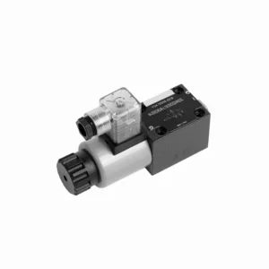
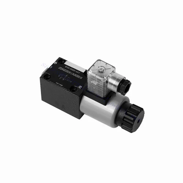
The M-SED series directional poppet hydraulic valve with solenoid actuation is a cutting-edge solution that provides precise control and optimal efficiency in hydraulic systems. With its innovative design, reliable performance, and advanced solenoid actuation, this valve offers enhanced fluid flow control, flexibility, and compatibility with various industrial applications.
The M-SED series directional poppet hydraulic valve with solenoid actuation is a reliable and efficient solution for hydraulic systems. With its directional poppet design, advanced solenoid actuation, versatility, and high flow capacity, this valve offers precise control, enhanced efficiency, and compatibility with various applications. The M-SED series valve delivers optimal performance and reliability by following the recommended usage methods and adhering to regular maintenance practices. Upgrade your hydraulic system with the M-SED series directional poppet hydraulic valve and experience enhanced control, efficiency, and productivity.
M-SED Series Directional Poppet Hydraulic Valve With Solenoid Actuation Key Characteristics:
- Projekt zaworu kierunkowego:
- The M-SED series valve features a directional poppet design, ensuring reliable and efficient fluid flow control.
- Umożliwia szybki czas reakcji i precyzyjną regulację kierunku przepływu cieczy, co zwiększa ogólną wydajność systemu.
- Napęd elektromagnetyczny:
- This hydraulic valve is equipped with advanced solenoid actuation and provides remote and automated control capabilities.
- Elektrozawór umożliwia szybkie i precyzyjne przełączanie pomiędzy różnymi ścieżkami przepływu, co zwiększa wydajność operacyjną.
- Wszechstronność i kompatybilność:
- The M-SED series valve is highly versatile and compatible with various hydraulic systems and applications.
- Można go bezproblemowo zintegrować z maszynami przemysłowymi, urządzeniami mobilnymi i systemami automatyki, co pozwala na zwiększenie wydajności.
- Wysoka przepustowość:
- With its robust design and optimized flow paths, the M-SED series valve offers high flow capacity.
- Zapewnia wydajny transfer płynów, redukując spadki ciśnienia i maksymalizując przepustowość układu.
M-SED Series Directional Poppet Hydraulic Valve With Solenoid Actuation Parameter:
| Specyfikacje | NG6 | NG10 | ||
| Pozycja instalacji | Fakultatywny | |||
| Temperatura otoczenia | ℃ | -30 do +50 (uszczelki NBR) | ||
| -20 do +50 (uszczelki FKM) | ||||
| Waga | Dwa trójdrożne zawory elektromagnetyczne kierunkowe | kg | 1.5 | 2.6 |
| Dwa czterodrożne zawory elektromagnetyczne kierunkowe | kg | 2.3 | 3.9 | |
| Maksymalne ciśnienie robocze | bar | 350 | 350 | |
| Maksymalny przepływ | l/min | 25 | 40 | |
| Płyn | Olej mineralny odpowiedni do uszczelnień NBR i FKM | |||
| Ester fosforanowy do uszczelnień FKM | ||||
| Zakres temperatur cieczy | ℃ | -30 do +80 (uszczelki NBR) | ||
| -20 do +80 (uszczelki FKM) | ||||
| Zakres lepkości | mm2/S | 2,8 do 500 | ||
| Stopień skażenia | Maximum permissible degree of fluid contamination: Class 9. NAS 1638 | Maksymalny dopuszczalny stopień zanieczyszczenia płynem: Klasa 9. NAS 1638 lub 20/18/15, ISO4406 | ||
M-SED Series Directional Poppet Hydraulic Valve With Solenoid Actuation Advantages:
• Bezpośredni zawór odcinający elektromagnetyczny
• Montaż powierzchni czołowej odbywa się zgodnie z normami DIN 24340 A, ISO 4401 i CETOP-RP 121H
• Brak wycieków
• Szybkie przełączanie pod wysokim ciśnieniem
• Replacing the coil does not require opening the sealed chamber
• Cewka elektromagnesu może obracać się o 90°
• With manual emergency control optional
Usage Method Of M-SED Series Directional Poppet Hydraulic Valve With Solenoid Actuation:
- Ocena systemu:
- Przeprowadź dokładną ocenę układu hydraulicznego w celu określenia szczegółowych wymagań i parametrów operacyjnych.
- Consider factors such as flow rates, pressure ratings, and compatibility with the M-SED Series Valve.
- Wybór zaworu:
- Select the appropriate M-SED Series Valve variant based on the system requirements and specifications.
- Consider factors such as port size, voltage compatibility, and solenoid actuation parameters.
- Instalacja:
- Follow the manufacturer’s instructions for proper installation of the M-SED Series Valve in the hydraulic system.
- Aby zapobiec wyciekom i zagwarantować optymalną wydajność, należy zadbać o bezpieczny montaż, właściwe wyrównanie i stosowne uszczelnienie.
- Połączenia elektryczne:
- Podłącz przewody sterujące zaworem elektromagnetycznym do odpowiedniego źródła zasilania, postępując zgodnie z zalecanymi wytycznymi dotyczącymi okablowania.
- Należy zadbać o właściwą biegunowość i izolację, aby zapobiec awariom elektrycznym lub zagrożeniom bezpieczeństwa.
How Does A Hydraulic Counterbalance Valve Work?
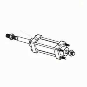
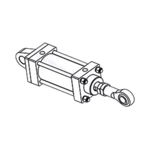
A hydraulic counterbalance valve is a type of valve used in hydraulic systems to control the motion and stability of loads. It is commonly employed in applications where there is a need to control the descent or lowering of heavy loads, such as in cranes, excavators, and material handling equipment. The primary function of a counterbalance valve is to provide controlled resistance to the downward movement of a load, preventing it from free-falling or dropping uncontrollably.
Here’s how a hydraulic counterbalance valve works:
- Flow Control:
- When the load is lifted, hydraulic fluid flows from the pump to the cylinder, raising the load.
- The counterbalance valve is installed in the line between the cylinder and the directional control valve.
- Check Valve Function:
- The counterbalance valve incorporates a built-in check valve that allows the free flow of oil from the pump to the cylinder during the lifting phase.
- The check valve opens, permitting fluid flow in one direction while blocking it in the opposite direction.
- Counterbalance Function:
- When the lifting action is complete and the directional control valve is shifted to the neutral position, the counterbalance valve comes into play.
- As the load starts to descend, the pressure at the cylinder port of the counterbalance valve increases.
- Pilot Pressure:
- The increased pressure at the cylinder port acts on a pilot piston within the counterbalance valve.
- This pilot pressure opposes the spring force in the valve, causing the valve to open gradually.
- Flow Restriction:
- As the counterbalance valve opens, it creates a restricted flow path for the hydraulic fluid returning from the cylinder.
- This restriction slows down the rate of fluid flow, providing controlled resistance against the load’s downward motion.
- Load Control:
- The counterbalance valve modulates the flow restriction based on the load’s weight and the desired speed of descent.
- By adjusting the spring tension or using adjustable counterbalance valves, the valve’s setting can be customized for specific applications.
- Stability and Safety:
- The counterbalance valve ensures stability and safety by preventing the load from dropping too quickly or causing uncontrolled movements.
- It maintains the load in a stable position, even when external forces or variations in the hydraulic system occur.
Możliwości i pojemność fabryki:
(1) Montaż
Dysponujemy najwyższej klasy niezależną platformą badawczo-rozwojową. Warsztat produkcji siłowników hydraulicznych posiada cztery półautomatyczne linie montażowe siłowników podnoszących i jedną automatyczną linię montażową siłowników przechyłu, o projektowanej rocznej zdolności produkcyjnej 1 miliona sztuk. Specjalny warsztat cylindrów jest wyposażony w różne specyfikacje półautomatycznego systemu montażu czyszczącego o projektowanej rocznej zdolności produkcyjnej 200 000 i wyposażony w słynny sprzęt do obróbki CNC, centrum obróbcze, specjalny sprzęt do precyzyjnej obróbki cylindrów, robot spawalniczy, automatyczna maszyna czyszcząca, automatyczna maszyna do montażu cylindrów i automatyczna linia produkcyjna do malowania. Istniejący krytyczny sprzęt składa się z ponad 300 zestawów. Optymalna alokacja i efektywne wykorzystanie zasobów sprzętowych zapewniają wymagania dotyczące dokładności produktów i spełniają potrzeby wysokiej jakości produktów.


(2) Obróbka
Warsztat obróbki skrawaniem jest wyposażony w niestandardowe centrum tokarskie z pochyloną szyną, centrum obróbcze, szybkobieżną honownicę, robota spawalniczego i inny powiązany sprzęt, który może obsługiwać przetwarzanie rur cylindrycznych o maksymalnej średnicy wewnętrznej 400 mm i maksymalnej długości 6 metrów.

(3) Spawanie

(4) Malowanie i powlekanie
Z małymi i średnimi automatycznymi liniami do powlekania farbami na bazie wody, w celu osiągnięcia automatycznego załadunku i rozładunku robota oraz automatycznego natryskiwania, wydajność projektowa 4000 sztuk na zmianę;
Posiadamy również półautomatyczną linię do produkcji farb do dużych cylindrów napędzaną łańcuchem napędowym, o wydajności 60 skrzyń na zmianę.


(5) Testowanie
Dysponujemy najwyższej klasy urządzeniami kontrolnymi i stanowiskami testowymi, aby zapewnić, że wydajność cylindra spełnia wymagania.

Jesteśmy jednym z najlepszych producentów cylindrów hydraulicznych. Oferujemy kompleksową ofertę cylindrów hydraulicznych. Dostarczamy również… przekładnie rolnicze. Eksportowaliśmy nasze produkty do klientów na całym świecie i zdobyliśmy dobrą reputację dzięki najwyższej jakości produktów i usług posprzedażnych. Zapraszamy klientów w kraju i za granicą do kontaktu z nami w celu negocjacji biznesowych, wymiany informacji i współpracować z nami!