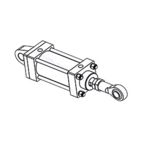
30SD08-26 Solenoid Directional Valve
30SD08-26 Solenoid Directional Valve

It is introducing the 30SD08-26 solenoid directional valve, a powerful and versatile component designed to optimize hydraulic system performance. With its advanced features and robust construction, this valve delivers enhanced efficiency, precision, and reliability.
The 30SD08-26 solenoid directional valve is a game-changer for hydraulic systems, offering enhanced efficiency, precision, and reliability. With precise fluid flow control, high flow capacity, quick response time, and durable construction, this valve empowers your hydraulic system to perform optimally. By following the recommended usage methods and maintenance guidelines, you can unlock the full potential of the 30SD08-26 solenoid directional valve, achieving seamless control, improved productivity, and optimized operation. Upgrade your hydraulic system today with the 30sd08-26 solenoid directional valve and experience the efficiency and precision it brings to your operations.
30SD08-26 Solenoid Directional Valve Characteristics:
- Precise Fluid Flow Control:
- The 30SD08-26 solenoid directional valve offers exceptional precision in controlling fluid flow, ensuring accurate and reliable system operation.
- With its precise control capabilities, this valve allows for seamless adjustment of fluid flow rates, facilitating optimal performance in various industrial applications.
- Wysoka przepustowość:
- Equipped with a high flow capacity design, the 30SD08-26 solenoid directional valve can handle substantial fluid volumes efficiently.
- This feature ensures smooth and reliable operation, even in applications that require high flow rates, enabling your hydraulic system to perform at its best.
- Szybki czas reakcji:
- The 30SD08-26 solenoid directional valve boasts a rapid response time, enabling precise control adjustments and quick changes in fluid flow direction.
- Experience improved system efficiency and responsiveness, allowing swift and accurate modifications to meet your operational needs.
- Durability and Reliability:
- Built with rugged construction, the 30SD08-26 solenoid directional Valve is designed to withstand demanding operating conditions.
- Its durable materials and robust design minimize downtime, reduce maintenance requirements, and ensure long-lasting performance.
30SD08-25 Solenoid Directional Valve Parameter:
| Ciśnienie znamionowe | 207 barów (3000 psi) | |
| Przepływ szczytowy | Zobacz wykres wydajności | |
| Effective orifice size | 0.81 mm (0.032 in.) | |
| Wyciek wewnętrzny | ≤3 krople/min@207bar | |
| Obciążenie cewki | Ciągły od 85% do 115% napięcia znamionowego | |
| Początkowy pobór prądu cewki przy 20°C | 1,4 A przy 12 V DC; 0,7 A przy 24 V DC | |
| Minimalne napięcie wciągania | 85% o wartości nominalnej przy ciśnieniu 207 barów (3000 psi) | |
| Wgłębienie | VC08-2 | |
| Płyn | Mineralne lub syntetyczne o właściwościach smarujących | |
| Zakres temperatury płynu ℃ | -54 do 107 ℃ (uszczelki poliuretanowe) | |
| -40 do 100 ℃ (uszczelki Buna N) | ||
| -26 do 204 ℃ (uszczelki fluorowęglowe) | ||
| Zakres lepkości | 7,4 do 420 mm2/S | |
| Stopień skażenia | Minimalny poziom zanieczyszczenia to ISO4406 poziom 20/18/14, a w celu wydłużenia żywotności zaleca się poziom 17/15/13 | |
30SD08-25 Solenoid Directional Valve Advantages:
• Cewka o pracy ciągłej
• Wydajna konstrukcja armatury mokrej
• Wkłady są wymienne pod względem napięcia
• Opcjonalne wodoodporne cewki elektryczne o klasie ochrony IP69K
• Wspólna wnęka przemysłowa
• Utwardzone części zapewniające długą żywotność i niskie wycieki
Usage Method Of 30SD08-25 Solenoid Directional Valve:
- Ocena systemu:
- Begin by evaluating your hydraulic system’s requirements, including flow rates, pressure levels, and system dynamics.
- Determine if the 30SD08-26 Solenoid Directional Valve aligns with your specific needs, considering its precision, flow capacity, and compatibility with other system components.
- Wybór zaworu:
- Select the appropriate variant of the 30SD08-26 solenoid directional valve based on your system parameters and performance requirements.
- Consider factors such as flow capacity, pressure ratings, and compatibility to ensure seamless integration and optimal functionality.
- Instalacja:
- Follow the manufacturer’s installation instructions carefully to ensure proper placement and secure mounting of the valve.
- Position the valve correctly within the hydraulic system, considering fluid flow direction and accessibility for maintenance purposes.
- Połączenia elektryczne:
- Connect the solenoid valve to the designated power source according to the manufacturer’s specifications.
- Ensure that the electrical connections are secure, adhering to safety standards and guidelines.
How To Hook Up A Hydraulic Flow Control Valve?
To hook up a hydraulic flow control valve, follow these steps:
- Identify Valve Type: Determine the specific type of flow control valve you are working with. Common types include needle valves, adjustable flow control valves, or pressure-compensated flow control valves. Ensure that the valve is suitable for your application and compatible with your hydraulic system.
- Gather Required Tools and Materials: Collect the necessary tools and materials, including appropriate hydraulic fittings, adapters, hoses, and wrenches.
- Prepare the Hydraulic System: Shut down the hydraulic system and relieve any pressure in the system by activating the relief valve or retracting any hydraulic cylinders. This step is crucial for safety.
- Identify Flow Direction: Identify the flow direction in your hydraulic system. Typically, the flow direction is indicated by arrows on the hydraulic components. Ensure that you understand the correct flow direction before proceeding.
- Locate Installation Point: Determine the optimal location to install the flow control valve in your hydraulic system. Consider factors such as accessibility, proximity to the actuator or hydraulic component, and ease of adjustment.
- Mount the Valve: Securely mount the flow control valve in the chosen location using appropriate brackets or clamps. Ensure the valve is positioned correctly, aligning the inlet and outlet ports with the flow direction.
- Connect the Inlet and Outlet Ports: Attach hydraulic hoses or tubing to the inlet and outlet ports of the flow control valve. Use suitable hydraulic fittings and adapters to create a leak-free connection. Tighten the connections using wrenches to ensure a secure fit, but avoid over-tightening.
- Adjust the Flow Control: Depending on the type of flow control valve, it may have adjustable features such as a needle valve or a flow control knob. Adjust the valve according to your desired flow rate or speed. Refer to the manufacturer’s instructions for specific adjustment procedures.
- Przetestuj system: Once the flow control valve is installed and adjusted, slowly restore hydraulic system pressure. Test the system to ensure that the flow control valve is functioning correctly. Monitor the flow rate or speed of the hydraulic actuator to verify that it is within the desired range.
- Fine-tune and Monitor: Adjust the flow control valve to achieve the desired flow rate or speed. Regularly monitor the hydraulic system for leaks, pressure inconsistencies, or unusual behavior.
Możliwości i pojemność fabryki:
(1) Montaż
Dysponujemy najwyższej klasy niezależną platformą badawczo-rozwojową. Warsztat produkcji siłowników hydraulicznych posiada cztery półautomatyczne linie montażowe siłowników podnoszących i jedną automatyczną linię montażową siłowników przechyłu, o projektowanej rocznej zdolności produkcyjnej 1 miliona sztuk. Specjalny warsztat cylindrów jest wyposażony w różne specyfikacje półautomatycznego systemu montażu czyszczącego o projektowanej rocznej zdolności produkcyjnej 200 000 i wyposażony w słynny sprzęt do obróbki CNC, centrum obróbcze, specjalny sprzęt do precyzyjnej obróbki cylindrów, robot spawalniczy, automatyczna maszyna czyszcząca, automatyczna maszyna do montażu cylindrów i automatyczna linia produkcyjna do malowania. Istniejący krytyczny sprzęt składa się z ponad 300 zestawów. Optymalna alokacja i efektywne wykorzystanie zasobów sprzętowych zapewniają wymagania dotyczące dokładności produktów i spełniają potrzeby wysokiej jakości produktów.


(2) Obróbka
Warsztat obróbki skrawaniem jest wyposażony w niestandardowe centrum tokarskie z pochyloną szyną, centrum obróbcze, szybkobieżną honownicę, robota spawalniczego i inny powiązany sprzęt, który może obsługiwać przetwarzanie rur cylindrycznych o maksymalnej średnicy wewnętrznej 400 mm i maksymalnej długości 6 metrów.

(3) Spawanie

(4) Malowanie i powlekanie
Z małymi i średnimi automatycznymi liniami do powlekania farbami na bazie wody, w celu osiągnięcia automatycznego załadunku i rozładunku robota oraz automatycznego natryskiwania, wydajność projektowa 4000 sztuk na zmianę;
Posiadamy również półautomatyczną linię do produkcji farb do dużych cylindrów napędzaną łańcuchem napędowym, o wydajności 60 skrzyń na zmianę.


(5) Testowanie
Dysponujemy najwyższej klasy urządzeniami kontrolnymi i stanowiskami testowymi, aby zapewnić, że wydajność cylindra spełnia wymagania.

Jesteśmy jednym z najlepszych producentów cylindrów hydraulicznych. Oferujemy kompleksową ofertę cylindrów hydraulicznych. Dostarczamy również… przekładnie rolnicze. Eksportowaliśmy nasze produkty do klientów na całym świecie i zdobyliśmy dobrą reputację dzięki najwyższej jakości produktów i usług posprzedażnych. Zapraszamy klientów w kraju i za granicą do kontaktu z nami w celu negocjacji biznesowych, wymiany informacji i współpracować z nami!