

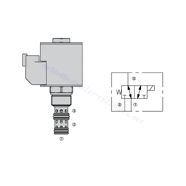
30SD10-34 Solenoid Directional Valve

The 30SD10-34 solenoid directional valve is a cutting-edge industrial component designed to provide precise and reliable fluid control in a wide range of applications. With its advanced features, durable construction, and user-friendly design, this solenoid directional valve offers enhanced performance and efficiency.
The 30SD10-34 solenoid directional valve is a reliable and versatile component that offers precise fluid control in industrial applications. Its robust construction, precision control, and reliable performance make it an ideal choice for enhancing the efficiency and productivity of your fluid control systems. By following the recommended usage methods and maintenance guidelines, you can ensure optimal performance and longevity of the 30SD10-34 solenoid directional valve in your industrial operations.
30SD10-34 Solenoid Directional Valve Characteristics:
- Robust Construction: The 30SD10-34 solenoid directional valve is built with high-quality materials and meticulous craftsmanship, ensuring durability and longevity. Its robust construction allows it to withstand demanding industrial environments, providing reliable performance even under harsh conditions.
- Versatile Functionality: This solenoid directional valve offers versatile functionality, making it suitable for various applications. It effectively controls the direction of fluid flow, allowing precise and efficient operation in different industrial systems.
- Precision Control: With exceptional precision, the 30SD10-34 solenoid directional valve enables accurate control over fluid flow. It allows for precise regulation and adjustment of fluid direction and pressure, ensuring optimal performance and efficiency in industrial processes.
- Reliable Performance: This solenoid directional valve delivers reliable performance, minimizing the risk of system failures or interruptions. It operates dependably, contributing to increased productivity and reduced downtime in industrial operations.
30SD10-34 Solenoid Directional Valve Parameter:
| Ciśnienie znamionowe | 207 barów (3000 psi) | |
| Proof pressure | 350 bar (5075 psi) | |
| Przepływ szczytowy | 22.7 L/min (6 gpm) | |
| Płyn | Mineralne lub syntetyczne o właściwościach smarujących | |
| Zakres temperatur ℃ | -54 do 107 ℃ (uszczelki poliuretanowe) | |
| -40 do 100 ℃ (uszczelki Buna N) | ||
| -26 do 204 ℃ (uszczelki fluorowęglowe) | ||
| Zakres lepkości | 7,4 do 420 mm2/S | |
| Stopień skażenia | Minimalny poziom zanieczyszczenia to ISO4406 poziom 20/18/14, a w celu wydłużenia żywotności zaleca się poziom 17/15/13 | |
| Wyciek wewnętrzny | ≤ 115 mL/min@207bar | |
| Wgłębienie | VC10-3 | |
| Obciążenie cewki | Ciągły od 85% do 115% napięcia znamionowego | |
| Response time | First indication of change of state with 100% voltage supplied at80% of nominal flow rating:Energized: 60 msec. ; De-energized: 10 msec. | |
| Początkowy pobór prądu cewki przy 20°C | Cewka elektroniczna | 1,7 A przy 12 V DC; 0,85 A przy 24 V DC |
| Cewka D | 1,67 A przy 12 V DC; 0,83 A przy 24 V DC | |
| Minimalne napięcie wciągania | 85% nominalnej przy 207 barach | |
30SD10-34 Solenoid Directional Valve Advantages:
• Cewka o pracy ciągłej
• Wydajna konstrukcja armatury mokrej
• Wkłady są wymienne pod względem napięcia
• Opcjonalne wodoodporne cewki elektryczne o klasie ochrony IP69K
• All ports may be fully pressurized
• Wspólna wnęka przemysłowa
• Utwardzone części zapewniające długą żywotność i niskie wycieki
Usage Method Of 30SD10-34 Solenoid Directional Valve:
- Integration into System: Integrate the 30SD10-34 solenoid directional valve into the fluid control system following the manufacturer’s guidelines and specifications. Ensure proper alignment and connection between the valve and other system components to achieve optimal performance.
- Electrical Connection: Establish a secure electrical connection for the solenoid directional valve. Refer to the provided wiring diagram and ensure correct polarity to prevent any electrical malfunctions. Follow safety guidelines when working with electrical connections.
- Sterowanie kierunkiem przepływu cieczy: Wykorzystaj elektrozawór kierunkowy do sterowania kierunkiem przepływu cieczy. Zawór jest zazwyczaj wyposażony w dźwignię lub siłownik do ręcznej regulacji. Alternatywnie, można go zintegrować z automatycznym systemem sterowania w celu obsługi zdalnej.
- Pressure Adjustment: Employ the solenoid directional valve to regulate fluid pressure within the system. By adjusting the valve’s settings, you can achieve the desired pressure levels for optimal performance and efficiency.
How To Plumb Auto Cycle Hydraulic Valve?
Plumbing an auto-cycle hydraulic valve requires careful attention to ensure proper installation and functionality. Follow these steps to plumb an auto-cycle hydraulic valve effectively:
- Zbierz niezbędne narzędzia i materiały: Before you begin, make sure you have all the required tools and materials, including hydraulic hoses, fittings, adapters, Teflon tape, wrenches, and a hydraulic fluid reservoir.
- Identify The Valve Ports: Examine the auto-cycle hydraulic valve to identify the different ports. Typically, there will be inlet ports, outlet ports, and possibly additional ports for pressure relief or auxiliary functions.
- Determine The Hydraulic Fluid Flow Direction: Determine the desired flow direction of the hydraulic fluid through the valve. This information is crucial for correctly connecting the inlet and outlet ports.
- Install Fittings And Adapters: Install the appropriate fittings and adapters onto the valve ports. Ensure they are tightened securely, but be careful not to overtighten and damage the threads.
- Apply Teflon Tape: Wrap Teflon tape around the threads of the fittings and adapters. This helps create a tight seal and prevents leaks.
- Connect Hydraulic Hoses: Attach hydraulic hoses to the fittings and adapters on the valve ports. Ensure the hoses are suitable for the hydraulic system’s pressure rating and are of the correct length.
- Secure Hose Connections: Use hose clamps or other suitable methods to secure the hydraulic hoses to the fittings. This prevents the hoses from coming loose during operation.
- Route The Hydraulic hoses: Carefully route the hydraulic hoses to connect the auto-cycle hydraulic valve to the hydraulic fluid reservoir and other hydraulic components, such as cylinders or motors. Avoid sharp bends or kinks in the hoses that could restrict fluid flow.
- Check For Leaks: Once all connections are made, check for leaks. Start by slowly pressurizing the system and inspecting each connection point. If you notice any leaks, tighten the fittings or replace faulty components as necessary.
- Fill The Hydraulic Fluid Reservoir: Fill the hydraulic fluid reservoir with the recommended type and quantity of hydraulic fluid. Refer to the manufacturer’s guidelines for the appropriate fluid specifications.
- Bleed Air From The System: B bleed any air trapped in the hydraulic system to ensure proper operation. Follow the manufacturer’s instructions for bleeding procedures, which typically involve cycling the design and opening bleed valves.
- Test The System: With the plumbing complete, test the auto-cycle hydraulic valve and the overall system’s performance. Verify that the valve functions as intended and that fluid flow is smooth and consistent.
Możliwości i pojemność fabryki:
(1) Montaż
Dysponujemy najwyższej klasy niezależną platformą badawczo-rozwojową. Warsztat produkcji siłowników hydraulicznych posiada cztery półautomatyczne linie montażowe siłowników podnoszących i jedną automatyczną linię montażową siłowników przechyłu, o projektowanej rocznej zdolności produkcyjnej 1 miliona sztuk. Specjalny warsztat cylindrów jest wyposażony w różne specyfikacje półautomatycznego systemu montażu czyszczącego o projektowanej rocznej zdolności produkcyjnej 200 000 i wyposażony w słynny sprzęt do obróbki CNC, centrum obróbcze, specjalny sprzęt do precyzyjnej obróbki cylindrów, robot spawalniczy, automatyczna maszyna czyszcząca, automatyczna maszyna do montażu cylindrów i automatyczna linia produkcyjna do malowania. Istniejący krytyczny sprzęt składa się z ponad 300 zestawów. Optymalna alokacja i efektywne wykorzystanie zasobów sprzętowych zapewniają wymagania dotyczące dokładności produktów i spełniają potrzeby wysokiej jakości produktów.


(2) Obróbka
Warsztat obróbki skrawaniem jest wyposażony w niestandardowe centrum tokarskie z pochyloną szyną, centrum obróbcze, szybkobieżną honownicę, robota spawalniczego i inny powiązany sprzęt, który może obsługiwać przetwarzanie rur cylindrycznych o maksymalnej średnicy wewnętrznej 400 mm i maksymalnej długości 6 metrów.


(3) Spawanie


(4) Malowanie i powlekanie
Z małymi i średnimi automatycznymi liniami do powlekania farbami na bazie wody, w celu osiągnięcia automatycznego załadunku i rozładunku robota oraz automatycznego natryskiwania, wydajność projektowa 4000 sztuk na zmianę;
Posiadamy również półautomatyczną linię do produkcji farb do dużych cylindrów napędzaną łańcuchem napędowym, o wydajności 60 skrzyń na zmianę.


(5) Testowanie
Dysponujemy najwyższej klasy urządzeniami kontrolnymi i stanowiskami testowymi, aby zapewnić, że wydajność cylindra spełnia wymagania.


Jesteśmy jednym z najlepszych producentów cylindrów hydraulicznych. Oferujemy kompleksową ofertę cylindrów hydraulicznych. Dostarczamy również… przekładnie rolnicze. Eksportowaliśmy nasze produkty do klientów na całym świecie i zdobyliśmy dobrą reputację dzięki najwyższej jakości produktów i usług posprzedażnych. Zapraszamy klientów w kraju i za granicą do kontaktu z nami w celu negocjacji biznesowych, wymiany informacji i współpracować z nami!