30SD10-40 Zawór elektromagnetyczny kierunkowy
Jako jeden z producentów, dostawców i eksporterów produktów mechanicznych, oferujemy cylindry hydrauliczne i wiele innych produktów.
Prosimy o kontakt w celu uzyskania szczegółowych informacji.
Poczta:sales@hydraulic-cylinders.net
Producent dostawca eksporter siłowników hydraulicznych.
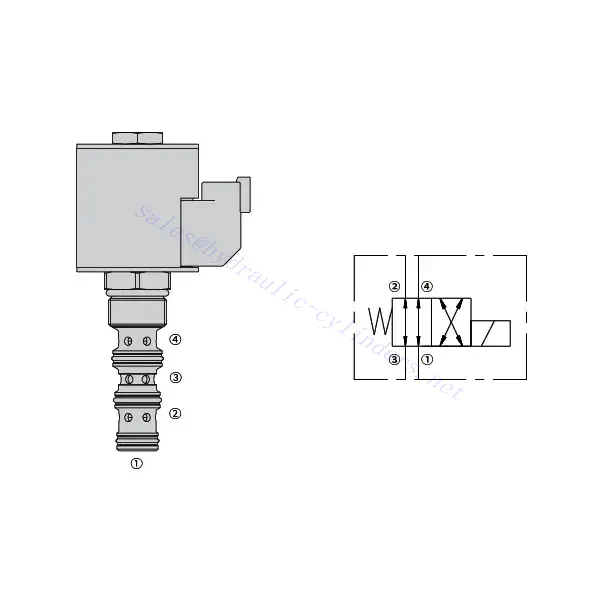
30SD10-40 Zawór elektromagnetyczny kierunkowy
Elektrozawór kierunkowy 30SD10-40 to wysokowydajny komponent przemysłowy, zaprojektowany z myślą o precyzyjnym i niezawodnym sterowaniu przepływem cieczy w różnorodnych zastosowaniach. Dzięki zaawansowanym funkcjom, trwałej konstrukcji i przyjaznej dla użytkownika konstrukcji, ten elektrozawór kierunkowy oferuje zwiększoną wydajność i niezawodność działania.
Elektrozawór kierunkowy 30SD10-40 to niezawodny i wszechstronny element, który zapewnia precyzyjną kontrolę przepływu cieczy w zastosowaniach przemysłowych. Jego solidna konstrukcja, precyzyjna kontrola i niezawodne działanie zwiększają wydajność i produktywność w systemach sterowania przepływem cieczy. Przestrzegając zalecanych metod użytkowania i instrukcji konserwacji, można zapewnić optymalną wydajność i trwałość elektrozaworu kierunkowego 30SD10-40 w procesach przemysłowych.
Charakterystyka zaworu elektromagnetycznego 30SD10-40:
- Solidna konstrukcja: Elektromagnetyczny zawór kierunkowy 30SD10-40 został wykonany z wyjątkową dbałością o szczegóły i wysokiej jakości materiałów, co gwarantuje trwałość i długowieczność. Jego solidna konstrukcja pozwala mu sprostać wymagającym warunkom przemysłowym, gwarantując niezawodną pracę nawet w trudnych warunkach.
- Wszechstronna funkcjonalność: Ten elektromagnetyczny zawór kierunkowy oferuje wszechstronną funkcjonalność, dzięki czemu nadaje się do szerokiego zakresu zastosowań. Skutecznie steruje kierunkiem przepływu cieczy, umożliwiając precyzyjną i wydajną pracę w różnych systemach przemysłowych.
- Precyzyjna kontrola: Elektromagnetyczny zawór kierunkowy 30SD10-40 zapewnia wyjątkową precyzję sterowania przepływem cieczy. Umożliwia precyzyjną regulację i regulację kierunku przepływu cieczy oraz jej ciśnienia, gwarantując optymalną wydajność i efektywność w procesach przemysłowych.
- Niezawodna wydajność: Ten elektromagnetyczny zawór kierunkowy zapewnia niezawodną wydajność, minimalizując ryzyko awarii lub przerw w pracy systemu. Działa niezawodnie, przyczyniając się do wzrostu wydajności i skrócenia przestojów w procesach przemysłowych.
Parametry zaworu elektromagnetycznego 30SD10-40:
| Ciśnienie znamionowe | 207 barów (3000 psi) | |
| Przepływ szczytowy | 23 l/min (6 galonów na minutę) | |
| Płyn | Mineralne lub syntetyczne o właściwościach smarujących | |
| Zakres temperatur ℃ | -54 do 107 ℃ (uszczelki poliuretanowe) | |
| -40 do 100 ℃ (uszczelki Buna N) | ||
| -26 do 204 ℃ (uszczelki fluorowęglowe) | ||
| Zakres lepkości | 7,4 do 420 mm2/S | |
| Stopień skażenia | Minimalny poziom zanieczyszczenia to ISO4406 poziom 20/18/14, a w celu wydłużenia żywotności zaleca się poziom 17/15/13 | |
| Wyciek wewnętrzny | ≤ 82 ml/min@207bar | |
| Wgłębienie | VC10-4 | |
| Obciążenie cewki | Ciągły od 85% do 115% napięcia znamionowego | |
| Początkowy pobór prądu cewki przy 20°C | Cewka elektroniczna | 1,7 A przy 12 V DC; 0,85 A przy 24 V DC |
| Cewka D | 1,67 A przy 12 V DC; 0,83 A przy 24 V DC | |
| Minimalne napięcie wciągania | 85% nominalnej przy 207 barach | |
Zalety zaworu elektromagnetycznego 30SD10-40:
• Cewka o pracy ciągłej
• Wkłady są wymienne pod względem napięcia
• Opcjonalne wodoodporne cewki elektryczne o klasie ochrony IP69K
• Wydajna konstrukcja armatury mokrej
• Wspólna wnęka przemysłowa
• Utwardzone części zapewniające długą żywotność
Sposób użycia zaworu elektromagnetycznego kierunkowego 30SD10-40 :
- Integracja z systemem: Zintegruj elektromagnetyczny zawór kierunkowy 30SD10-40 z systemem sterowania przepływem cieczy, postępując zgodnie z wytycznymi i specyfikacjami producenta. Zapewnij prawidłowe ustawienie i połączenie zaworu z innymi elementami systemu, aby uzyskać optymalną wydajność.
- Połączenie elektryczne: Zapewnij bezpieczne połączenie elektryczne elektrozaworu kierunkowego. Postępuj zgodnie z załączonym schematem okablowania i upewnij się, że biegunowość jest prawidłowa, aby zapobiec awariom elektrycznym. Podczas pracy z połączeniami elektrycznymi należy przestrzegać zasad bezpieczeństwa.
- Sterowanie kierunkiem przepływu cieczy: Wykorzystaj elektrozawór kierunkowy do sterowania kierunkiem przepływu cieczy. Zawór jest zazwyczaj wyposażony w dźwignię lub siłownik do ręcznej regulacji. Alternatywnie, można go zintegrować z automatycznym systemem sterowania w celu obsługi zdalnej.
- Regulacja ciśnienia: Użyj elektrozaworu kierunkowego do regulacji ciśnienia płynu w układzie. Dostosuj ustawienia zaworu, aby uzyskać pożądany poziom ciśnienia i zapewnić optymalną wydajność i efektywność.
Jak czytać schematy zaworów hydraulicznych?
Czytanie schematów zaworów hydraulicznych wymaga podstawowej znajomości symboli hydraulicznych i ich znaczenia. Oto kroki ułatwiające czytanie schematów zaworów hydraulicznych:
- Zapoznaj się z symbolami hydraulicznymi: Schematy hydrauliczne wykorzystują symbole graficzne do przedstawiania różnych komponentów i funkcji. Typowe symbole to kwadraty oznaczające zawory, linie oznaczające rury lub węże, strzałki oznaczające kierunek przepływu oraz okręgi oznaczające urządzenia sterujące ciśnieniem lub przepływem. Przed przystąpieniem do dalszych czynności upewnij się, że rozumiesz znaczenie tych symboli.
- Zidentyfikuj typy zaworów: Poszukaj symboli zaworów na schemacie. Zawory mogą być reprezentowane przez kwadraty o różnych kształtach i orientacjach. Na przykład, kwadrat z ukośną linią oznacza zawór zwrotny, a kwadrat ze strzałką w środku – zawór sterujący kierunkiem przepływu.
- Określ funkcję zaworu: Każdy symbol zaworu wskazuje jego konkretną funkcję. Zawory sterujące kierunkiem przepływu płynu hydraulicznego określają kierunek przepływu, natomiast zawory sterujące ciśnieniem regulują poziom ciśnienia. Zawory sterujące przepływem regulują natężenie przepływu płynu, a zawory zwrotne umożliwiają przepływ tylko w jednym kierunku.
- Zwróć uwagę na połączenia zaworów: Zwróć uwagę na linie lub strzałki wchodzące i wychodzące z symbolu zaworu. Linie te reprezentują ścieżki przepływu płynu hydraulicznego. Strzałki wskazują kierunek przepływu, a linie łączące zawory i inne elementy wskazują połączenia.
- Przeanalizuj położenie zaworów: Niektóre schematy zaworów hydraulicznych zawierają symbole ilustrujące ich położenie. Symbole te zazwyczaj przedstawiają suwak lub dźwignię zaworu w różnych pozycjach, takich jak otwarta, zamknięta lub częściowo otwarta. Zrozumienie położenia zaworów pomaga określić ścieżki przepływu i stan układu hydraulicznego.
- Rozważ dodatkowe symbole i adnotacje: Schematy hydrauliczne mogą zawierać dodatkowe symbole i adnotacje wskazujące na manometry, przepływomierze, filtry, akumulatory lub inne elementy. Zapoznaj się z tymi symbolami i ich znaczeniem, aby uzyskać pełne zrozumienie systemu.
- Podążaj ścieżkami przepływu: Prześledź ścieżki przepływu od hydraulicznego źródła zasilania przez różne zawory i komponenty do siłownika lub żądanego wyjścia. Zrozum, jak zawory oddziałują na siebie i jak sterują przepływem, ciśnieniem i kierunkiem cieczy, aby uzyskać pożądane działanie systemu.
- Zapoznaj się z legendą lub kluczem: Schemat powinien zawierać legendę lub klucz wyjaśniający znaczenie każdego symbolu użytego na diagramie. W przypadku napotkania nieznanych symboli lub wątpliwości co do ich znaczenia, należy zapoznać się z legendą w celu uzyskania wyjaśnień.
- W razie potrzeby poszukaj dodatkowych zasobów: Jeśli chcesz lepiej zrozumieć schematy zaworów hydraulicznych, rozważ skorzystanie z podręczników hydrauliki, źródeł internetowych lub skonsultowanie się ze specjalistami w dziedzinie hydrauliki, którzy mogą udzielić wskazówek i wyjaśnień dostosowanych do Twoich indywidualnych potrzeb.
Możliwości i pojemność fabryki:
(1) Montaż
Dysponujemy najwyższej klasy niezależną platformą badawczo-rozwojową. Warsztat produkcji siłowników hydraulicznych posiada cztery półautomatyczne linie montażowe siłowników podnoszących i jedną automatyczną linię montażową siłowników przechyłu, o projektowanej rocznej zdolności produkcyjnej 1 miliona sztuk. Specjalny warsztat cylindrów jest wyposażony w różne specyfikacje półautomatycznego systemu montażu czyszczącego o projektowanej rocznej zdolności produkcyjnej 200 000 i wyposażony w słynny sprzęt do obróbki CNC, centrum obróbcze, specjalny sprzęt do precyzyjnej obróbki cylindrów, robot spawalniczy, automatyczna maszyna czyszcząca, automatyczna maszyna do montażu cylindrów i automatyczna linia produkcyjna do malowania. Istniejący krytyczny sprzęt składa się z ponad 300 zestawów. Optymalna alokacja i efektywne wykorzystanie zasobów sprzętowych zapewniają wymagania dotyczące dokładności produktów i spełniają potrzeby wysokiej jakości produktów.


(2) Obróbka
Warsztat obróbki skrawaniem jest wyposażony w niestandardowe centrum tokarskie z pochyloną szyną, centrum obróbcze, szybkobieżną honownicę, robota spawalniczego i inny powiązany sprzęt, który może obsługiwać przetwarzanie rur cylindrycznych o maksymalnej średnicy wewnętrznej 400 mm i maksymalnej długości 6 metrów.

(3) Spawanie

(4) Malowanie i powlekanie
Z małymi i średnimi automatycznymi liniami do powlekania farbami na bazie wody, w celu osiągnięcia automatycznego załadunku i rozładunku robota oraz automatycznego natryskiwania, wydajność projektowa 4000 sztuk na zmianę;
Posiadamy również półautomatyczną linię do produkcji farb do dużych cylindrów napędzaną łańcuchem napędowym, o wydajności 60 skrzyń na zmianę.


(5) Testowanie
Dysponujemy najwyższej klasy urządzeniami kontrolnymi i stanowiskami testowymi, aby zapewnić, że wydajność cylindra spełnia wymagania.

Jesteśmy jednym z najlepszych producentów cylindrów hydraulicznych. Oferujemy kompleksową ofertę cylindrów hydraulicznych. Dostarczamy również… przekładnie rolnicze. Eksportowaliśmy nasze produkty do klientów na całym świecie i zdobyliśmy dobrą reputację dzięki najwyższej jakości produktów i usług posprzedażnych. Zapraszamy klientów w kraju i za granicą do kontaktu z nami w celu negocjacji biznesowych, wymiany informacji i współpracować z nami!
Siłownik hydrauliczny Zastosowanie:
