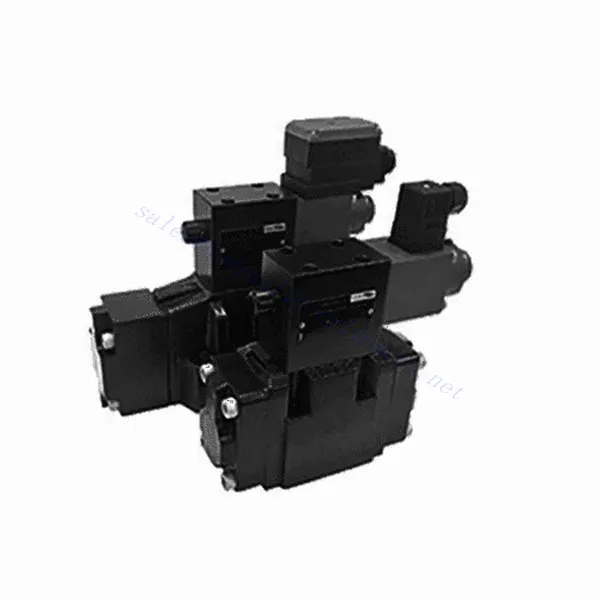
Seria 3DRE/M(E) 3-drożny hydrauliczny zawór redukcyjny proporcjonalny sterowany pilotem
Jako jeden z producentów, dostawców i eksporterów produktów mechanicznych, oferujemy cylindry hydrauliczne i wiele innych produktów.
Prosimy o kontakt w celu uzyskania szczegółowych informacji.
Poczta:sales@hydraulic-cylinders.net
Producent dostawca eksporter siłowników hydraulicznych.
Seria 3DRE/M(E) 3-drożny hydrauliczny zawór redukcyjny proporcjonalny sterowany pilotem
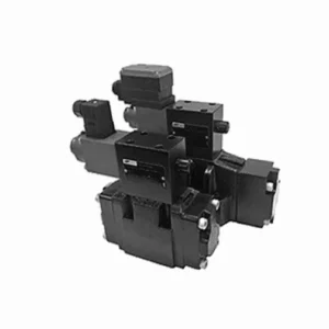
Trójdrożny, sterowany pilotem, proporcjonalny zawór hydrauliczny redukujący ciśnienie serii 3DRE/M(E) to najnowocześniejszy element hydrauliczny zaprojektowany z myślą o precyzyjnej kontroli ciśnienia w układach hydraulicznych. Dzięki zaawansowanej technologii sterowania proporcjonalnego sterowanego pilotem, zawór ten zapewnia precyzyjną regulację, wydajność i niezawodność.
Trójdrożny, proporcjonalny zawór hydrauliczny redukujący ciśnienie serii 3DRE/M(E) zapewnia precyzyjną kontrolę ciśnienia, wydajność i niezawodną pracę układów hydraulicznych. Dzięki zaawansowanej technologii sterowania proporcjonalnego i konfiguracji trójdrożnej, zawór ten oferuje wszechstronność i elastyczność w regulacji ciśnienia w różnych obwodach hydraulicznych. Przestrzegając zalecanych metod użytkowania i wskazówek dotyczących konserwacji, można zmaksymalizować korzyści i wydłużyć żywotność zaworu serii 3DRE/M(E), optymalizując kontrolę ciśnienia i ogólną wydajność układu hydraulicznego. Zmodernizuj swoją instalację hydrauliczną już dziś i ciesz się doskonałą regulacją ciśnienia dzięki trójdrożnemu, proporcjonalnemu zaworowi hydraulicznemu redukującemu ciśnienie serii 3DRE/M(E).
Główne cechy 3DRE/M(E) 3-drożnego zaworu hydraulicznego proporcjonalnego redukującego ciśnienie sterowanego pilotem:
- Sterowanie ciśnieniem proporcjonalnym:
- Zawór serii 3DRE/M(E) zapewnia precyzyjną i proporcjonalną kontrolę ciśnienia, umożliwiając dynamiczną regulację poziomu ciśnienia hydraulicznego.
- Funkcja ta zapewnia dokładną regulację ciśnienia, utrzymując stałe i bezpieczne ciśnienie w układzie hydraulicznym.
- Projekt pilotażowy:
- Dzięki konstrukcji sterowanej pilotem zawór zapewnia większą precyzję i szybkość reakcji przy sterowaniu ciśnieniem.
- Wykorzystuje zawór pilotowy do modulacji zaworu głównego, co pozwala na precyzyjną regulację i lepszą kontrolę redukcji ciśnienia.
- Konfiguracja 3-drożna:
- Zawór serii 3DRE/M(E) charakteryzuje się wszechstronną konfiguracją 3-drożną, zapewniającą elastyczność sterowania ciśnieniem w różnych obwodach hydraulicznych.
- Umożliwia jednoczesną redukcję ciśnienia w jednym obwodzie i jednoczesne dostarczanie ciśnienia do drugiego obwodu.
- Efektywna wydajność:
- Dzięki zastosowaniu zaawansowanej technologii sterowania proporcjonalnego zawór zapewnia wydajną pracę, optymalizując zużycie energii i redukując koszty eksploatacji.
- Minimalizuje wahania ciśnienia, zwiększając wydajność systemu i przyczyniając się do ogólnej produktywności.
Parametry 3DRE/M(E) 3-drożnego zaworu hydraulicznego redukującego ciśnienie proporcjonalnie sterowanego pilotem:
| Hydrauliczny | ||||||||
| Pozycja instalacji | opcjonalnie, najlepiej poziomo | |||||||
| Rozmiar | 6 | 10 | ||||||
| Waga | 4WRA…L2X | kg | 2 | 6.6 | ||||
| 4WRAE…L2X | 2.2 | 6.8 | ||||||
| Przepływ znamionowy qnom, gdy Δp = 10 barów | l/min | 7, 15, 26 | 30, 60 | |||||
| Histereza | % | ≤5 | ||||||
| Powtarzalność | % | ≤1 | ||||||
| Wrażliwość reakcji | % | ≤0,5 | ||||||
| Maksymalne ciśnienie robocze | Port s ABP | bar | 315 | |||||
| Port T | bar | 210 | ||||||
| Płyn | Olej mineralny odpowiedni do uszczelnień NBR i FKM | |||||||
| Ester fosforanowy do uszczelnień FKM | ||||||||
| Zakres temperatur cieczy | 4WRA…L2X | ℃ | -20℃ do 70℃ (-4°F do 158°F) | |||||
| 4WRAE…L2X | ℃ | -20℃ do 50℃ (-4° F do 122° F) | ||||||
| Zakres lepkości | mm²/s | 20 do 380 (najlepiej 30 do 46) | ||||||
| Stopień skażenia | NAS1638 klasa 9 lub ISO 4406 klasa 20/18/15 | |||||||
| Dane elektryczne | ||||||||
| 1)elektromagnes | ||||||||
| Typ napięcia | DC | |||||||
| Sygnał wartości polecenia | ±10 V lub 4~20 mA | |||||||
| Maksymalny prąd na elektromagnes | A | 2.5 | 1.5 | 0.8 | ||||
| Rezystancja cewki | Wartość zimna | Ω | 2 | 4.8 | 19.5 | |||
| Maksymalna wartość ciepła | 3 | 7.2 | 28.8 | |||||
| Obowiązek | % | ED100% | ||||||
| Temperatura cewki | ℃ | 150 | ||||||
| Zabezpieczenie zaworu zgodnie z normą EN 60529 | IP 65 | |||||||
| 2)Elektronika sterująca | ||||||||
| Wzmacniacz | 4WRA…L2X | VT-VSPA2-L2X | ||||||
| 4WRAE…L2X | Zintegrowany z zaworem (OBE) | |||||||
| Napięcie robocze | Napięcie nominalne | VDC | 24 | |||||
| Dolna wartość graniczna | V | 21/22(4WRA), 19(4WRAE) | ||||||
| Górna wartość graniczna | V | 35 | ||||||
| Pobór prądu wzmacniacza | Imax | A | <1,8 | |||||
| Imax | A | 3 | ||||||
Zalety 3-drożnego proporcjonalnego zaworu hydraulicznego redukującego ciśnienie serii 3DREP(E):
• Zawór bezpieczeństwa sterowany pilotem służy do redukcji ciśnienia z P do A i funkcji przelewu z A do T.
• Stosowany do montażu na dolnej płycie pomocniczej, sterowany elektromagnesem proporcjonalnym.
• Powierzchnia montażowa zgodna z normami DIN24 340, typ A, ISO4401 i CETOP-RP 121H
• Można wybrać maksymalne ciśnienie bezpieczeństwa.
• Wyrównanie sprężyny szpuli
• Kontroler elektroniczny 3DRE: wzmacniacz zgodny ze specyfikacją karty europejskiej VT-VSPA1-1/VT-VSPD-1
• Punkt nastawy krzywa charakterystyki ciśnienia jest liniowa
• Zintegrowany sterownik elektroniczny serii 3DRE(M)E
• Wartość ustawienia spowodowana błędem produkcyjnym – odchylenie krzywej charakterystycznej ciśnienia jest niewielkie
• Nachylenie wzrostu i spadku ciśnienia można regulować niezależnie
Metoda użytkowania 3-drożnego proporcjonalnego zaworu hydraulicznego redukującego ciśnienie serii 3DREP(E):
- Ocena systemu:
- Oceń swój układ hydrauliczny i określ szczegółowe wymagania dotyczące kontroli ciśnienia dla każdego obwodu.
- Określ, czy zawór serii 3DRE/M(E) jest odpowiedni, biorąc pod uwagę jego zakres ciśnień, przepustowość i kompatybilność z Twoim systemem.
- Wybór zaworu:
- Wybierz odpowiedni wariant zaworu serii 3DRE/M(E) na podstawie parametrów swojego systemu, zakresu ciśnień i wymagań dotyczących przepływu.
- Należy wziąć pod uwagę maksymalne ciśnienie znamionowe, czas reakcji i warunki operacyjne.
- Instalacja:
- Dokładnie postępuj zgodnie z instrukcjami producenta dotyczącymi instalacji, aby zapewnić właściwe wyrównanie i bezpieczne mocowanie zaworu.
- Podłącz zawór do układu hydraulicznego, upewniając się, że połączenia są szczelne i kierunek przepływu jest prawidłowy.
- Regulacja ciśnienia:
- Wykorzystaj mechanizm sterujący zaworem pilotowym dostarczony wraz z zaworem serii 3DRE/M(E), aby dostosować pożądany poziom redukcji ciśnienia dla każdego obwodu.
- Stopniowo reguluj sterowanie zaworem pilotowym, aby uzyskać pożądaną kontrolę ciśnienia, monitorując odczyty manometrów i reakcję układu.
Jak regulować zawory hydrauliczne?
Regulacja zaworów hydraulicznych jest kluczowym zadaniem dla zapewnienia prawidłowej kontroli przepływu i wydajności systemu w zastosowaniach hydraulicznych. Oto przewodnik krok po kroku, jak regulować zawory hydrauliczne:
- Zidentyfikuj zawór:
- Określ typ zaworu hydraulicznego, który należy wyregulować: zawór bezpieczeństwa, zawór regulacji przepływu, zawór sterujący kierunkiem przepływu lub jakikolwiek inny typ.
- Znajdź zawór w swoim układzie hydraulicznym. Może on znajdować się w pobliżu pompy, w rozdzielaczu zaworów sterujących lub w określonych podzespołach hydraulicznych.
- Zbierz niezbędne narzędzia:
- Przed rozpoczęciem regulacji należy zgromadzić niezbędne narzędzia, takie jak klucz nastawny, śrubokręt, manometr (jeśli dotyczy) i wszelkie specjalistyczne narzędzia zalecane przez producenta zaworu.
- Zrozumienie funkcji zaworu:
- Zapoznaj się z przeznaczeniem i funkcją regulowanego zaworu. Szczegółowe informacje znajdziesz w dokumentacji technicznej zaworu lub w wytycznych producenta.
- Określ pożądane ustawienie:
- Określ pożądane ustawienie lub parametr, który chcesz osiągnąć poprzez regulację zaworu. Może to być ciśnienie, natężenie przepływu, kierunek lub dowolny inny regulowany parametr w zależności od typu zaworu.
- Kontrole wstępne:
- Przed przystąpieniem do jakichkolwiek regulacji należy upewnić się, że układ hydrauliczny jest pozbawiony ciśnienia. Można to zrobić, wyłączając układ i uwalniając ciśnienie resztkowe za pomocą odpowiednich zaworów.
- Uzyskaj dostęp do mechanizmu regulacji:
- Znajdź mechanizm regulacji zaworu. Może to być śruba ustalająca, nakrętka zabezpieczająca, pokrętło lub inne podobne urządzenie, w zależności od typu zaworu.
- W przypadku niektórych zaworów może być konieczne zdjęcie ochronnej nasadki lub pokrywy, aby uzyskać dostęp do mechanizmu regulacji.
- Wprowadź stopniowe zmiany:
- Używając odpowiedniego narzędzia, dokonaj niewielkich, przyrostowych regulacji zaworu, zgodnie z pożądanym ustawieniem.
- Postępuj zgodnie ze wskazówkami producenta, aby określić kierunek (zgodny z ruchem wskazówek zegara lub przeciwny do ruchu wskazówek zegara) i zakres wymaganej regulacji.
- Stopniowo wprowadzaj zmiany i okresowo sprawdzaj reakcję systemu, aby mieć pewność, że poruszasz się we właściwym kierunku.
- Testowanie i monitorowanie:
- Po każdej regulacji należy uruchomić układ hydrauliczny i obserwować jego działanie.
- Za pomocą odpowiednich narzędzi pomiarowych (manometru, przepływomierza itp.) sprawdź, czy zawór działa w żądanym zakresie.
- Monitoruj system pod kątem wszelkich nieprawidłowości lub nieoczekiwanego zachowania. W razie potrzeby dokonaj dalszych regulacji, aby precyzyjnie dostroić ustawienia zaworu.
- Zablokuj regulację (jeśli dotyczy):
- Po ustawieniu żądanej wartości należy zabezpieczyć mechanizm regulacji, aby zapobiec niezamierzonym zmianom.
- Można tego dokonać poprzez dokręcenie nakrętki zabezpieczającej, zabezpieczenie śruby ustalającej lub stosując inną metodę zalecaną przez producenta zaworu.
Możliwości i pojemność fabryki:
(1) Montaż
Dysponujemy najwyższej klasy niezależną platformą badawczo-rozwojową. Warsztat produkcji siłowników hydraulicznych posiada cztery półautomatyczne linie montażowe siłowników podnoszących i jedną automatyczną linię montażową siłowników przechyłu, o projektowanej rocznej zdolności produkcyjnej 1 miliona sztuk. Specjalny warsztat cylindrów jest wyposażony w różne specyfikacje półautomatycznego systemu montażu czyszczącego o projektowanej rocznej zdolności produkcyjnej 200 000 i wyposażony w słynny sprzęt do obróbki CNC, centrum obróbcze, specjalny sprzęt do precyzyjnej obróbki cylindrów, robot spawalniczy, automatyczna maszyna czyszcząca, automatyczna maszyna do montażu cylindrów i automatyczna linia produkcyjna do malowania. Istniejący krytyczny sprzęt składa się z ponad 300 zestawów. Optymalna alokacja i efektywne wykorzystanie zasobów sprzętowych zapewniają wymagania dotyczące dokładności produktów i spełniają potrzeby wysokiej jakości produktów.


(2) Obróbka
Warsztat obróbki skrawaniem jest wyposażony w niestandardowe centrum tokarskie z pochyloną szyną, centrum obróbcze, szybkobieżną honownicę, robota spawalniczego i inny powiązany sprzęt, który może obsługiwać przetwarzanie rur cylindrycznych o maksymalnej średnicy wewnętrznej 400 mm i maksymalnej długości 6 metrów.

(3) Spawanie

(4) Malowanie i powlekanie
Z małymi i średnimi automatycznymi liniami do powlekania farbami na bazie wody, w celu osiągnięcia automatycznego załadunku i rozładunku robota oraz automatycznego natryskiwania, wydajność projektowa 4000 sztuk na zmianę;
Posiadamy również półautomatyczną linię do produkcji farb do dużych cylindrów napędzaną łańcuchem napędowym, o wydajności 60 skrzyń na zmianę.


(5) Testowanie
Dysponujemy najwyższej klasy urządzeniami kontrolnymi i stanowiskami testowymi, aby zapewnić, że wydajność cylindra spełnia wymagania.

Jesteśmy jednym z najlepszych producentów cylindrów hydraulicznych. Oferujemy kompleksową ofertę cylindrów hydraulicznych. Dostarczamy również… przekładnie rolnicze. Eksportowaliśmy nasze produkty do klientów na całym świecie i zdobyliśmy dobrą reputację dzięki najwyższej jakości produktów i usług posprzedażnych. Zapraszamy klientów w kraju i za granicą do kontaktu z nami w celu negocjacji biznesowych, wymiany informacji i współpracować z nami!
Siłownik hydrauliczny Zastosowanie:
