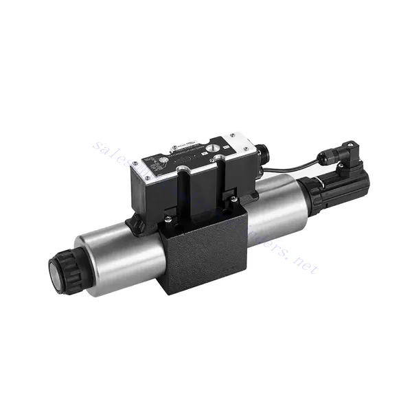
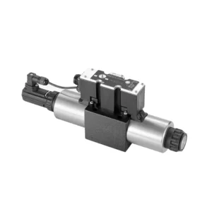
4WRE(E) Series Proportional Directional Hydraulic Valve
Jako jeden z producentów, dostawców i eksporterów produktów mechanicznych, oferujemy cylindry hydrauliczne i wiele innych produktów.
Prosimy o kontakt w celu uzyskania szczegółowych informacji.
Poczta:sales@hydraulic-cylinders.net
Producent dostawca eksporter siłowników hydraulicznych.
4WRE(E) Series Proportional Directional Hydraulic Valve
The 4WRE(E) series proportional directional hydraulic valve is a cutting-edge hydraulic component designed to deliver precise control and exceptional performance in hydraulic systems. This valve utilizes advanced proportional control technology to ensure accurate flow regulation and seamless directional changes.
The 4WRE(E) series proportional directional hydraulic valve empowers hydraulic systems with precise flow control, versatile directional changes, and energy efficiency. Its proportional control technology enables accurate and responsive flow adjustment, while the high flow capacity ensures reliable performance even in demanding applications. By following the recommended usage methods and maintenance guidelines, you can maximize the benefits and longevity of the 4WRE(E) series valve, elevating your hydraulic system to new levels of precision and performance. Upgrade your hydraulic setup today and experience the power of the 4WRE(E) series proportional directional hydraulic valve.
4WRE(E) Series Proportional Directional Hydraulic Valve Key Characteristics:
- Proportional Control Technology:
- The 4WRE(E) series valve features advanced proportional control technology, allowing for precise and proportional flow adjustment according to control signals.
- This feature enables accurate and responsive control, resulting in improved system performance and efficiency.
- Wszechstronna kontrola kierunkowa:
- With its proportional directional control capability, this valve offers versatile control over hydraulic fluid direction.
- It allows for seamless activation and deactivation of hydraulic components such as cylinders, motors, and actuators in different directions, enhancing system flexibility and productivity.
- Wysoka przepustowość:
- The 4WRE(E) series valve is designed to handle high flow rates, making it suitable for applications requiring substantial hydraulic power.
- Solidna konstrukcja gwarantuje niezawodną pracę nawet w trudnych warunkach, gwarantując spójną i wydajną kontrolę przepływu.
- Efektywność energetyczna:
- By employing advanced flow control mechanisms, this valve minimizes pressure drops and optimizes energy usage.
- Pomaga zmniejszyć zużycie energii, co przekłada się na oszczędności i korzyści dla środowiska.
4WRE(E) Series Proportional Directional Hydraulic Valve Parameter:
| Hydrauliczny | ||||
| Pozycja instalacji | opcjonalnie, najlepiej poziomo | |||
| Rozmiar | 6 | 10 | ||
| Waga | 4WRE…L2X | kg | 2.2 | 6.3 |
| 4WREE…L2X | 2.4 | 6.5 | ||
| Nominal flow qnom at Δp = 10 bar | l/min | 8 16 32 | 25 50 75 | |
| Histereza | % | ≤0.1 | ||
| Reversal span | % | ≤0.05 | ||
| Powtarzalność | % | ≤0.05 | ||
| Maksymalne ciśnienie robocze | Port s ABP | bar | 315 | |
| Port T | bar | 210 | ||
| Płyn | Olej mineralny odpowiedni do uszczelnień NBR i FKM | |||
| Ester fosforanowy do uszczelnień FKM | ||||
| Ambient air temperature range | 4WRA…L2X | ℃ | -20℃ to 70℃ (-4°F to 158°F) | |
| 4WRAE…L2X | ℃ | -20℃ to 50℃ (-4°F to 122°F) | ||
| Zakres lepkości | mm²/s | 20 do 380 (najlepiej 30 do 46) | ||
| Stopień skażenia | NAS1638 klasa 9 lub ISO 4406 klasa 20/18/15 | |||
| Dane elektryczne | ||||
| 1)elektromagnes | ||||
| Rozmiar | 6 | 10 | ||
| Typ napięcia | DC | |||
| Sygnał wartości polecenia | ±10 V lub 4~20 mA | |||
| Max.current per solenoid | A | 2.5 | ||
| Rezystancja cewki | Wartość zimna | Ω | 2.7 | 3.7 |
| Maksymalna wartość ciepła | 4.05 | 5.55 | ||
| Obowiązek | % | ED 100% | ||
| Temperatura cewki | ℃ | 150 | ||
| Zabezpieczenie zaworu zgodnie z normą EN 60529 | IP 65 | |||
| 2) Control electronics | ||||
| Wzmacniacz | 4WRE…L2X | VT-VSPA2-L2X | ||
| 4WREE…L2X | integrated(OBE) | |||
| Napięcie robocze | Napięcie nominalne | VDC | 24 | |
| Dolna wartość graniczna | V | 19.4 | ||
| Górna wartość graniczna | V | 35 | ||
| Pobór prądu wzmacniacza | Imax | A | < 2 | |
| Imax | A | 3 | ||
4WRE(E) Series Proportional Directional Hydraulic Valve Advantages:
• Zawór kierunkowy proporcjonalny o działaniu bezpośrednim, służący do sterowania przepływem i kierunkiem przepływu cieczy
• Instalacja typu panelowego
• Elektromagnes proporcjonalny uruchamia rdzeń zaworu poprzez połączenie gwintowane, a cewkę można wyjąć osobno
• Spool position feedback
• Opcjonalnie z wbudowanym wzmacniaczem, wejście typu 4WRAE…L2X może być A1 lub F1
• Wsparcie zasilania zewnętrznego wzmacniacza
Usage Method Of 4WRE(E) Series Proportional Directional Hydraulic Valve:
- Ocena systemu:
- Oceń swój układ hydrauliczny i określ szczegółowe wymagania dotyczące przepływu i sterowania kierunkowego.
- Determine if the 4WRE(E) series valve is suitable based on its flow capacity, pressure rating, and compatibility with your system.
- Wybór zaworu:
- Select the appropriate variant of the 4WRE(E) series valve based on your system parameters, flow requirements, and directional control needs.
- Należy wziąć pod uwagę takie czynniki, jak maksymalna szybkość przepływu, ciśnienie znamionowe, czas reakcji i warunki pracy.
- Instalacja:
- Należy dokładnie przestrzegać instrukcji producenta dotyczących instalacji, aby zapewnić właściwe wyrównanie i bezpieczne zamocowanie zaworu.
- Make leak-free connections and ensure correct flow direction alignment to guarantee optimal performance.
- Podłączenie sygnału sterującego:
- Podłącz przewody sygnału sterującego zaworu do odpowiedniego urządzenia sterującego, na przykład wzmacniacza proporcjonalnego lub elektronicznej jednostki sterującej.
- Należy zadbać o właściwe okablowanie i kompatybilność między zaworem a urządzeniem sterującym, aby zapewnić dokładną i responsywną kontrolę.
How To Adjust Valves With Hydraulic Lifters?
Regulacja luzu zaworowego w popychaczach hydraulicznych to kluczowa czynność konserwacyjna, która zapewnia prawidłową pracę silnika i zapobiega problemom takim jak głośna praca zaworów czy spadek mocy. Oto instrukcja krok po kroku, jak regulować luz zaworowy w popychaczach hydraulicznych:
- Przygotowanie:
- Przed rozpoczęciem regulacji należy upewnić się, że silnik jest wyłączony i zimny.
- Zapoznaj się z kolejnością zapłonu silnika i szczegółowymi parametrami luzu zaworowego podanymi przez producenta dla danego modelu silnika.
- Zidentyfikuj właściwy cylinder:
- Określ położenie zapłonu silnika, korzystając ze schematu kolejności zapłonu silnika.
- Zidentyfikuj cylinder odpowiadający konkretnemu zaworowi, który chcesz wyregulować.
- Pozycja cylindra:
- Obróć wał korbowy silnika ręcznie, używając klucza nasadowego lub wbudowanego mechanizmu obrotowego silnika.
- Ustaw cylinder, który chcesz wyregulować, w górnym martwym punkcie (GMP) suwu sprężania. Możesz to zrobić, ustawiając znaki rozrządu na kole pasowym wału korbowego lub używając narzędzia do blokowania tłoka.
- Odkręć wahacz:
- Znajdź dźwigienkę zaworową na konkretnym zaworze, który chcesz wyregulować.
- Odkręć nakrętkę wahacza lub śrubę regulacyjną za pomocą odpowiedniego klucza lub nasadki.
- Regulacja luzu zaworowego:
- Po poluzowaniu dźwigienki zaworowej można teraz wyregulować luz zaworowy. Luz zaworowy to luz między dźwigienką zaworową a trzonkiem zaworu.
- Użyj szczelinomierza do pomiaru luzu zaworowego. Włóż odpowiedni grubościomierz między dźwigienkę zaworową a trzonek zaworu.
- Jeśli luz jest zbyt ciasny, co oznacza, że szczelinomierz nie pasuje lub stawia zbyt duży opór, należy zwiększyć luz zaworowy. Jeśli luz jest zbyt luźny, co oznacza, że szczelinomierz wsuwa się zbyt łatwo, należy zmniejszyć luz zaworowy.
- Aby wyregulować luz zaworowy, należy odpowiednio dokręcić lub poluzować nakrętkę wahacza lub śrubę regulacyjną. Zalecany zakres regulacji można znaleźć w specyfikacji producenta.
- Sprawdź ponownie luz zaworowy:
- Po dokonaniu regulacji należy ponownie sprawdzić luz zaworowy za pomocą szczelinomierza, aby upewnić się, że mieści się on w zalecanych parametrach.
- W razie konieczności powtórz proces regulacji, aż do uzyskania prawidłowego luzu zaworowego.
- Powtórz dla pozostałych cylindrów:
- Przejdź do następnego cylindra w kolejności zapłonu i powtórz kroki od 4 do 6 dla każdego cylindra, który chcesz wyregulować.
- Przed przystąpieniem do regulacji luzu zaworowego należy pamiętać o obróceniu wału korbowego i ustawieniu każdego cylindra w górnym martwym punkcie suwu sprężania.
- Zabezpiecz wahacz:
- Po prawidłowym wyregulowaniu luzu zaworowego dla każdego cylindra dokręć nakrętkę dźwigienek zaworowych lub śrubę regulacyjną zgodnie z zalecanym przez producenta momentem obrotowym.
- Sprawdź dokładnie, czy luz zaworowy po dokręceniu mieści się w określonym zakresie.
- Kontrole końcowe:
- Obróć wał korbowy silnika kilka razy, aby upewnić się, że obraca się płynnie i sprawdź, czy nie słychać nietypowych dźwięków lub oporu.
- Uruchom silnik i sprawdź, czy zawory nie wydają nietypowych dźwięków. Jeśli usłyszysz nadmierne stukanie lub stukanie, sprawdź ponownie ustawienie luzu zaworowego.
Możliwości i pojemność fabryki:
(1) Montaż
Dysponujemy najwyższej klasy niezależną platformą badawczo-rozwojową. Warsztat produkcji siłowników hydraulicznych posiada cztery półautomatyczne linie montażowe siłowników podnoszących i jedną automatyczną linię montażową siłowników przechyłu, o projektowanej rocznej zdolności produkcyjnej 1 miliona sztuk. Specjalny warsztat cylindrów jest wyposażony w różne specyfikacje półautomatycznego systemu montażu czyszczącego o projektowanej rocznej zdolności produkcyjnej 200 000 i wyposażony w słynny sprzęt do obróbki CNC, centrum obróbcze, specjalny sprzęt do precyzyjnej obróbki cylindrów, robot spawalniczy, automatyczna maszyna czyszcząca, automatyczna maszyna do montażu cylindrów i automatyczna linia produkcyjna do malowania. Istniejący krytyczny sprzęt składa się z ponad 300 zestawów. Optymalna alokacja i efektywne wykorzystanie zasobów sprzętowych zapewniają wymagania dotyczące dokładności produktów i spełniają potrzeby wysokiej jakości produktów.


(2) Obróbka
Warsztat obróbki skrawaniem jest wyposażony w niestandardowe centrum tokarskie z pochyloną szyną, centrum obróbcze, szybkobieżną honownicę, robota spawalniczego i inny powiązany sprzęt, który może obsługiwać przetwarzanie rur cylindrycznych o maksymalnej średnicy wewnętrznej 400 mm i maksymalnej długości 6 metrów.

(3) Spawanie

(4) Malowanie i powlekanie
Z małymi i średnimi automatycznymi liniami do powlekania farbami na bazie wody, w celu osiągnięcia automatycznego załadunku i rozładunku robota oraz automatycznego natryskiwania, wydajność projektowa 4000 sztuk na zmianę;
Posiadamy również półautomatyczną linię do produkcji farb do dużych cylindrów napędzaną łańcuchem napędowym, o wydajności 60 skrzyń na zmianę.


(5) Testowanie
Dysponujemy najwyższej klasy urządzeniami kontrolnymi i stanowiskami testowymi, aby zapewnić, że wydajność cylindra spełnia wymagania.

Jesteśmy jednym z najlepszych producentów cylindrów hydraulicznych. Oferujemy kompleksową ofertę cylindrów hydraulicznych. Dostarczamy również… przekładnie rolnicze. Eksportowaliśmy nasze produkty do klientów na całym świecie i zdobyliśmy dobrą reputację dzięki najwyższej jakości produktów i usług posprzedażnych. Zapraszamy klientów w kraju i za granicą do kontaktu z nami w celu negocjacji biznesowych, wymiany informacji i współpracować z nami!
Siłownik hydrauliczny Zastosowanie:
