
4WRKE Series Pilot Operated Proportional Directional Hydraulic Valve
Jako jeden z producentów, dostawców i eksporterów produktów mechanicznych, oferujemy cylindry hydrauliczne i wiele innych produktów.
Prosimy o kontakt w celu uzyskania szczegółowych informacji.
Poczta:sales@hydraulic-cylinders.net
Producent dostawca eksporter siłowników hydraulicznych.
4WRKE Series Pilot Operated Proportional Directional Hydraulic Valve
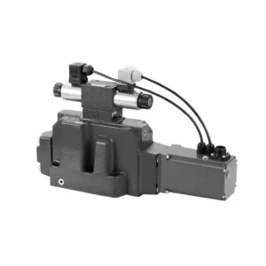
The 4WRKE series pilot-operated proportional directional hydraulic valve is a cutting-edge hydraulic component designed to provide superior precision, control, and efficiency in hydraulic systems. With its advanced pilot-operated proportional control technology, this valve enables accurate flow regulation and seamless directional changes.
The 4WRKE series pilot-operated proportional directional hydraulic valve empowers hydraulic systems with precise flow control, versatile directional changes, and energy efficiency. Its pilot-operated proportional control technology ensures accurate and responsive flow adjustment, while the high flow capacity guarantees reliable performance even in demanding applications. By following the recommended usage methods and maintenance guidelines, you can maximize the benefits and longevity of the 4WRKE series valve, elevating your hydraulic system to new levels of precision and control. Upgrade your hydraulic setup today and experience the power of the 4wrke series pilot-operated proportional directional hydraulic valve.
4WRKE Series Pilot Operated Proportional Directional Hydraulic Valve Key Characteristics:
- Sterowanie proporcjonalne sterowane pilotem
- The 4WRKE series valve utilizes pilot-operated proportional control technology, allowing precise and proportional flow adjustment based on control signals.
- Funkcja ta zapewnia dokładną i responsywną kontrolę, co przekłada się na lepszą wydajność systemu, mniejsze zużycie energii i większą produktywność.
- Wszechstronna kontrola kierunkowa
- Zawór ten zapewnia wszechstronną kontrolę kierunku przepływu płynu hydraulicznego, dzięki czemu nadaje się do szerokiej gamy zastosowań.
- Umożliwia bezproblemową aktywację i dezaktywację podzespołów hydraulicznych, takich jak cylindry, silniki i siłowniki, w różnych kierunkach, zwiększając elastyczność i zdolność adaptacji systemu.
- Wysoka przepustowość
- The 4WRKE series valve is engineered to handle high flow rates, making it ideal for applications that require substantial hydraulic power.
- Solidna konstrukcja gwarantuje niezawodną pracę nawet w trudnych warunkach, gwarantując spójną i wydajną kontrolę przepływu.
- Efektywność energetyczna
- Dzięki zastosowaniu sterowania proporcjonalnego sterowanego pilotem zawór ten minimalizuje spadki ciśnienia i optymalizuje zużycie energii.
- Pomaga zmniejszyć zużycie energii, co przekłada się na oszczędności i korzyści dla środowiska.
4WRKE Series Pilot Operated Proportional Directional Hydraulic Valve Parameter:
| Ogólny | |||||||||
| Rozmiar | 10 | 16 | 25 | 27 | 32 | 35 | |||
| Installation and commissioning guidelines | opcjonalnie, najlepiej poziomo | ||||||||
| Zakres temperatur przechowywania | ℃ | – 20 to + 80 | |||||||
| Zakres temperatur otoczenia | ℃ | -20 to + 50 | |||||||
| Waga | kg | 8.7 | 11.2 | 16.8 | 20 | 37.2 | 72 | ||
| Hydrauliczny ( measured at p=100bar,with HLP46 at ϑoil =40℃ ±5℃) | |||||||||
| Ciśnienie robocze | -Pilot control valve | Pilot oil supply | bar | 25 to 315 | |||||
| -Main valve | Port PAB | bar | Up to 315 | Up to 350 | Up to 350 | Up to 210 | Up to 350 | Up to 350 | |
| Ciśnienie powrotne | Port T
(Pilot oil drain) |
Internal | bar | Static < 10 | |||||
| External | bar | Up to 315 | Up to 250 | Up to 250 | Up to 210 | Up to 250 | Up to 250 | ||
| Port Y | bar | Static < 10 | |||||||
| Nominal flow qVnom ±10% at Δp=10bar (Δp = valve pressure differential) |
l/min | 25 50 | – 125 | – 220 | – – | – 440 | – | ||
| 100 | 180 | 350 | 500 | 600 | 1000 | ||||
| Flow of main valve (max. permissible) | l/min | 170 | 460 | 870 | 1000 | 1600 | 3000 | ||
| Pilot oil flow at port X or Y with a step form of input signal from 0 to 100 % (315 bar) | l/min | 4.1 | 8.5 | 11.7 | 11.7 | 13 | 13 | ||
| Płyn ciśnieniowy | Mineral oil(HL,HLP)to DIN 51 524 Phosphate ester (HFD-R) | ||||||||
| Zakres temperatur cieczy | ℃ | 10 to 80, preferably 40 to 50 | |||||||
| Zakres lepkości | mm2/S | 20 to 380, preferably 30 to 45 | |||||||
| Stopień skażenia | Maximum permissible degree of contamination: NAS 1638. | A filter with a minimum retention rate of βx = 75 is recommended | |||||||
| Pilot control valve | Class 7 | x = 5 | |||||||
| Zawór główny | Class 9 | x = 7 | |||||||
| Histereza | % | ≤1 | |||||||
| Wrażliwość reakcji | % | ≤0,5 | |||||||
| Elektryczny | |||||||||
| Typ napięcia | DC | ||||||||
| Połączenie elektryczne | Plug-in connector to DIN EN175 201-804 | ||||||||
| Power, max. | W | 72 (average = 24W) | |||||||
| Elektronika sterująca | Integrated into the valve | ||||||||
4WRKE Series Pilot Operated Proportional Directional Hydraulic Valve Advantages:
• Pilot-operated two-stage proportional directional valve with electrical position feedback of the main spool, used to control the size and direction of the liquid flow
• Sub-plate mounting type connection structure, connection size conforms to ISO 4401 standard
• Spring centred main spool
• With integrated proportional amplifier
• The pilot control is a single-stage proportional directional valve
• The pilot valve is a threaded proportional solenoid, and the coil can be disassembled separately
Usage Method Of 4WRKE Series Pilot Operated Proportional Directional Hydraulic Valve:
- Ocena systemu
- Oceń swój układ hydrauliczny i określ szczegółowe wymagania dotyczące przepływu i sterowania kierunkowego.
- Determine if the 4WRKE Series Valve is suitable based on its flow capacity, pressure rating, and compatibility with your system.
- Wybór zaworu
- Select the appropriate variant of the 4WRKE Series Valve based on your system parameters, flow requirements, and directional control needs.
- Należy wziąć pod uwagę takie czynniki, jak maksymalna szybkość przepływu, ciśnienie znamionowe, czas reakcji i warunki pracy.
- Instalacja
- Należy dokładnie przestrzegać instrukcji producenta dotyczących instalacji, aby zapewnić właściwe wyrównanie i bezpieczne zamocowanie zaworu.
- Wykonaj szczelne połączenia i zadbaj o prawidłowy kierunek przepływu, aby zagwarantować optymalną wydajność.
- Podłączenie sygnału sterującego
- Podłącz przewody sygnału sterującego zaworu do odpowiedniego urządzenia sterującego, na przykład wzmacniacza proporcjonalnego lub elektronicznej jednostki sterującej.
- Należy zadbać o właściwe okablowanie i kompatybilność między zaworem a urządzeniem sterującym, aby zapewnić dokładną i responsywną kontrolę.
How To Clean Hydraulic Valve Lifters?
Cleaning hydraulic valve lifters is an important maintenance task that helps ensure proper engine performance and reduce noise caused by dirt or debris buildup. Here’s a step-by-step guide on how to clean hydraulic valve lifters:
- Zbierz niezbędne narzędzia i materiały:
- New engine oil
- Czyste szmatki lub ręczniki
- Engine degreaser or parts cleaner
- Small brush or toothbrush
- Plastic container or tray
- Przygotowanie:
- Allow the engine to cool down completely before starting the cleaning process.
- Remove the valve cover or covers to access the hydraulic valve lifters. Refer to the manufacturer’s instructions or a repair manual for your specific engine to locate and remove the valve cover(s) properly.
- Removal of Hydraulic Valve Lifters:
- Identify the hydraulic valve lifters in the engine.
- One at a time, carefully remove the hydraulic valve lifters from their respective locations. Depending on your engine, you may need to remove other components or parts to access the lifters.
- Place each lifter in a plastic container or tray in the order they were removed. This will help ensure they are reinstalled correctly later.
- Cleaning the Lifters:
- Pour a small amount of engine degreaser or parts cleaner into a container.
- Place one hydraulic valve lifter into the container, ensuring it is fully submerged in the cleaner.
- Allow the lifter to soak for the recommended duration specified by the cleaner manufacturer. This usually ranges from 15 minutes to an hour.
- Use a small brush or toothbrush to gently scrub the lifter’s exterior surfaces, removing any deposits or dirt.
- Rinse the lifter thoroughly with clean water to remove any remaining cleaner or debris.
- Dry the lifter using a clean rag or towel. Ensure there are no traces of moisture before reinstallation.
- Reinstallation:
- Apply a small amount of fresh engine oil to the cleaned lifter’s exterior surface.
- Carefully place the lifter back into its original position in the engine, ensuring it is properly aligned and seated.
- Repeat the cleaning process for each hydraulic valve lifter, following the same steps.
- Once all the lifters are cleaned and reinstalled, make sure they are secured properly.
- Ponowny montaż:
- Reinstall the valve cover(s) according to the manufacturer’s instructions.
- Double-check that all components and parts are properly secured and tightened.
- Test and Inspection:
- Start the engine and let it run for a few minutes to ensure proper operation and to allow the lifters to refill with oil.
- Listen for any abnormal noises or ticking sounds that could indicate further issues.
- If noise or performance problems persist, it may be necessary to consult a professional mechanic for further diagnosis and repair.
Możliwości i pojemność fabryki:
(1) Montaż
Dysponujemy najwyższej klasy niezależną platformą badawczo-rozwojową. Warsztat produkcji siłowników hydraulicznych posiada cztery półautomatyczne linie montażowe siłowników podnoszących i jedną automatyczną linię montażową siłowników przechyłu, o projektowanej rocznej zdolności produkcyjnej 1 miliona sztuk. Specjalny warsztat cylindrów jest wyposażony w różne specyfikacje półautomatycznego systemu montażu czyszczącego o projektowanej rocznej zdolności produkcyjnej 200 000 i wyposażony w słynny sprzęt do obróbki CNC, centrum obróbcze, specjalny sprzęt do precyzyjnej obróbki cylindrów, robot spawalniczy, automatyczna maszyna czyszcząca, automatyczna maszyna do montażu cylindrów i automatyczna linia produkcyjna do malowania. Istniejący krytyczny sprzęt składa się z ponad 300 zestawów. Optymalna alokacja i efektywne wykorzystanie zasobów sprzętowych zapewniają wymagania dotyczące dokładności produktów i spełniają potrzeby wysokiej jakości produktów.


(2) Obróbka
Warsztat obróbki skrawaniem jest wyposażony w niestandardowe centrum tokarskie z pochyloną szyną, centrum obróbcze, szybkobieżną honownicę, robota spawalniczego i inny powiązany sprzęt, który może obsługiwać przetwarzanie rur cylindrycznych o maksymalnej średnicy wewnętrznej 400 mm i maksymalnej długości 6 metrów.

(3) Spawanie

(4) Malowanie i powlekanie
Z małymi i średnimi automatycznymi liniami do powlekania farbami na bazie wody, w celu osiągnięcia automatycznego załadunku i rozładunku robota oraz automatycznego natryskiwania, wydajność projektowa 4000 sztuk na zmianę;
Posiadamy również półautomatyczną linię do produkcji farb do dużych cylindrów napędzaną łańcuchem napędowym, o wydajności 60 skrzyń na zmianę.


(5) Testowanie
Dysponujemy najwyższej klasy urządzeniami kontrolnymi i stanowiskami testowymi, aby zapewnić, że wydajność cylindra spełnia wymagania.

Jesteśmy jednym z najlepszych producentów cylindrów hydraulicznych. Oferujemy kompleksową ofertę cylindrów hydraulicznych. Dostarczamy również… przekładnie rolnicze. Eksportowaliśmy nasze produkty do klientów na całym świecie i zdobyliśmy dobrą reputację dzięki najwyższej jakości produktów i usług posprzedażnych. Zapraszamy klientów w kraju i za granicą do kontaktu z nami w celu negocjacji biznesowych, wymiany informacji i współpracować z nami!
Siłownik hydrauliczny Zastosowanie:
