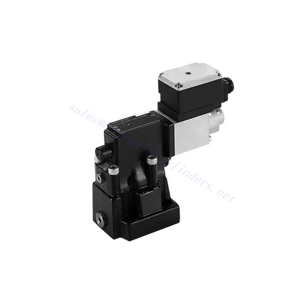
Zawór bezpieczeństwa proporcjonalny serii DBE/M(E)
Jako jeden z producentów, dostawców i eksporterów produktów mechanicznych, oferujemy cylindry hydrauliczne i wiele innych produktów.
Prosimy o kontakt w celu uzyskania szczegółowych informacji.
Poczta:sales@hydraulic-cylinders.net
Producent dostawca eksporter siłowników hydraulicznych.
Zawór bezpieczeństwa proporcjonalny serii DBE/M(E)
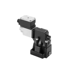
Przedstawiamy proporcjonalny zawór bezpieczeństwa serii DBE/M(E) – innowacyjny element hydrauliczny zaprojektowany z myślą o precyzyjnej i wydajnej regulacji ciśnienia w szerokim zakresie zastosowań przemysłowych. Dzięki zaawansowanym funkcjom, wyjątkowej wydajności i trwałej konstrukcji, zawór ten oferuje rozwiązanie optymalizujące wydajność systemu i zwiększające ogólną produktywność.
Proporcjonalny zawór bezpieczeństwa serii DBE/M(E) zapewnia precyzyjną i wydajną regulację ciśnienia w układach hydraulicznych. Dzięki wyjątkowej regulacji proporcjonalnej, funkcji redukcji ciśnienia, wysokiej przepustowości i wszechstronności, zawór ten zapewnia precyzyjną regulację ciśnienia, chroni podzespoły układu i poprawia ogólną wydajność. Przestrzegając zalecanych metod użytkowania i instrukcji konserwacji, możesz w pełni wykorzystać potencjał tego zaworu i osiągnąć optymalne rezultaty w zastosowaniach hydraulicznych. Zmodernizuj swój system regulacji ciśnienia już dziś, wybierając proporcjonalny zawór bezpieczeństwa serii DBE/M(E) i ciesz się zwiększoną precyzją i wydajnością.
Charakterystyka proporcjonalnego zaworu bezpieczeństwa serii DBE/M(E):
- Sterowanie proporcjonalne:
- Zawór serii DBE/M(E) wyróżnia się sterowaniem proporcjonalnym, umożliwiając precyzyjną regulację poziomu ciśnienia zgodnie z konkretnymi wymaganiami systemu.
- Ta zaawansowana funkcja sterowania zapewnia dokładną regulację ciśnienia, co ułatwia efektywną i zoptymalizowaną pracę.
- Funkcja redukcji ciśnienia:
- Zawór ten, zaprojektowany z myślą o redukcji ciśnienia, skutecznie reguluje ciśnienie poprzez przekierowanie nadmiaru przepływu płynu w celu utrzymania pożądanej wartości zadanej.
- Uwalniając nadmierne ciśnienie, zawór chroni podzespoły systemu przed potencjalnymi uszkodzeniami, gwarantując niezawodną i bezpieczną pracę.
- Wysoka przepustowość:
- Zawór serii DBE/M(E) charakteryzuje się dużą przepustowością, dzięki czemu nadaje się do zastosowań wymagających znacznych objętości płynu.
- Obsługa dużych przepływów gwarantuje wydajną pracę nawet w wymagających warunkach przemysłowych.
- Wszechstronność:
- Zawór ten zapewnia wszechstronność integracji systemu i jest kompatybilny z szeroką gamą konfiguracji i zastosowań hydraulicznych.
- Jego zdolność adaptacji pozwala na bezproblemową integrację z istniejącymi systemami, minimalizując przestoje i zwiększając ogólną wydajność.
Parametry proporcjonalnego zaworu bezpieczeństwa serii DBE/M(E):
| Ogólny | ||||
| Płyn | Olej mineralny odpowiedni do uszczelnień NBR i FKM | |||
| Ester fosforanowy do uszczelnień FKM | ||||
| Zakres temperatur cieczy | ℃ | -30 do +80 (uszczelki NBR) | ||
| -20 do +80 (uszczelki FKM) | ||||
| Zakres lepkości | mm2/S | 2,8 do 380 | ||
| Stopień skażenia | Maksymalny dopuszczalny stopień zanieczyszczenia płynem: Klasa 9. NAS 1638 lub 20/18/15, ISO4406 | |||
| Maksymalne ciśnienie robocze | 315 bar | |||
| Porty A, B, X | bar | 50; 100; 200; 315 | ||
| Maksymalne ciśnienie ustawienia | bar | W odniesieniu do przepływu (Q) patrz krzywe charakterystyczne | ||
| Min. ustawialne ciśnienie | =Minimalne ciśnienie do ustawienia | |||
| Min. ustawialne ciśnienie przy wartości polecenia 0 | Oddzielne i bezciśnieniowe do zbiorników | |||
| Port powrotu ciśnienia oleju Y | bar | Ustawienie ciśnienia | Zakres ciśnienia poniżej maksymalnego ciśnienia bezpieczeństwa | |
| Maksymalne ciśnienie bezpieczeństwa (regulowane bezstopniowo) | 50 bar | 10-60+20 bar | ||
| 100 bar | 10-120+20 bar | |||
| 200 bar | 10-220+20 bar | |||
| 315 bar | 10-340+20 bar | |||
| Maksymalny stan bezpieczeństwa ustawienia ciśnienia | Gdy ciśnienie znamionowe wynosi 50 barów, pomiędzy 60 barów i 80 barów | |||
| Gdy ciśnienie znamionowe wynosi 100 barów, od barów do 140 barów | ||||
| Gdy ciśnienie znamionowe wynosi 200 barów, w zakresie od 220 barów do 240 barów | ||||
| Gdy ciśnienie znamionowe wynosi 315 barów, pomiędzy 340 barów i 360 barów | ||||
| Rozmiar | 10 | 25 | 32 | |
| Maksymalny przepływ | 200 | 400 | 600 | |
| Olej pilotowy (do zaworu pilotowego) | l/min | 0,7 do 2 | ||
| Liniowość | l/min | ±3,5% | ||
| Powtarzalność | <±2% | |||
| Histereza | z shimmy | bez shimmy | ||
| ±1,5% P max (200Hz, amplituda 200mAsss) | ±4,5% P max | |||
| Czas przełączania | 30~150 ms (zależnie od systemu) | |||
| Dane elektryczne | ||||
| Moc | DC | |||
| Min. prąd elektromagnesu | mama | 100 | ||
| Maksymalny prąd elektromagnesu | mama | 800 | ||
| Rezystancja cewki | 19,5Ω przy 20℃, maks. wartość ciepła: 28,8Ω | |||
| Status pracy | Ciągły | |||
| Maksymalny zakres temperatur otoczenia | +50℃ | |||
| Połączenie elektryczne | Złącze wtykowe wg DIN 43 650/2 +SL/PG11 | |||
| Izolacja zgodna z DIN 40 050 | IP 65 | |||
| Wzmacniacz | VT2000 | |||
Zalety zaworów bezpieczeństwa proporcjonalnego serii DBE/M(E):
• Stosowany do montażu na dolnej płycie pomocniczej
• Montaż powierzchni czołowej odbywa się zgodnie z normami DIN24340 E i ISO 6264
• Stosowany w montażu bloków kanałów olejowych
• Cztery zakresy ciśnienia
• Konstrukcja zabezpieczająca przed najwyższym ciśnieniem (opcjonalnie)
• Pasujący wzmacniacz elektroniczny typu VT-2000 (należy zamówić osobno)
Metoda użytkowania proporcjonalnego zaworu bezpieczeństwa serii DBE/M(E):
- Ocena systemu:
- Zacznij od oceny wymagań swojego układu hydraulicznego, biorąc pod uwagę natężenie przepływu, zakres ciśnień i dynamikę układu.
- Sprawdź, czy proporcjonalna regulacja ciśnienia oferowana przez zawór serii DBE6X(E) odpowiada potrzebom Twojego systemu.
- Wybór zaworu:
- Wybierz odpowiedni wariant zaworu serii DBE6X(E) na podstawie parametrów swojego systemu i wymagań dotyczących wydajności.
- Aby zapewnić optymalną funkcjonalność, należy wziąć pod uwagę takie czynniki, jak przepustowość, zakres ciśnień i kompatybilność z innymi komponentami systemu.
- Instalacja:
- Należy dokładnie przestrzegać instrukcji producenta dotyczących instalacji, aby zapewnić właściwe umiejscowienie i bezpieczne mocowanie zaworu.
- Należy prawidłowo umiejscowić zawór w układzie hydraulicznym, biorąc pod uwagę takie czynniki, jak kierunek przepływu cieczy i dostępność w celu konserwacji.
- Ustawienie ciśnienia:
- Ustaw pożądany poziom ciśnienia poprzez regulację mechanizmu sterującego zaworu zgodnie z wytycznymi producenta.
- Upewnij się, że wartość zadana odpowiada konkretnym wymaganiom Twojego systemu.
Jak wymienić wkład zaworu prysznicowego?
Wymiana wkładu w zaworze prysznicowym to stosunkowo prosty proces, który może pomóc rozwiązać problemy takie jak przecieki, nierównomierna temperatura wody czy niskie ciśnienie. Oto instrukcja krok po kroku, jak wymienić wkład w zaworze prysznicowym:
- Zbierz niezbędne narzędzia i materiały:
- Wymienny wkład zaworu prysznicowego
- Klucz nastawny lub szczypce
- Śrubokręt (jeśli wymagany)
- Taśma do gwintów rurowych lub kit hydrauliczny (jeśli to konieczne)
- Ręczniki lub szmaty
- Wyłącz dopływ wody:
- Znajdź główny zawór doprowadzający wodę do prysznica i zamknij go. Zawór ten zazwyczaj znajduje się w pobliżu wodomierza lub w piwnicy.
- Przygotuj miejsce pracy:
- Rozłóż ręczniki lub szmatki pod prysznicem, aby zatrzymać wodę i zanieczyszczenia, które mogą spaść w trakcie mycia.
- Zdejmij wszystkie uchwyty prysznicowe lub osłony, aby uzyskać dostęp do wkładu zaworowego. W zależności od modelu prysznica może to wymagać odkręcenia lub podważenia osłony.
- Wyjmij istniejący wkład:
- Za pomocą klucza nastawnego lub szczypiec poluzuj i zdejmij nakrętkę mocującą wkład.
- Po odkręceniu nakrętki ostrożnie wyciągnij stary wkład z korpusu zaworu. W niektórych przypadkach może być konieczne delikatne podważenie go śrubokrętem.
- Zainstaluj nowy wkład:
- Weź wkład zamienny i wyrównaj go z korpusem zaworu, upewniając się, że wszystkie wypustki i rowki pasują do siebie.
- Wciśnij wkład mocno w korpus zaworu, aż zostanie całkowicie osadzony.
- Ponowny montaż prysznica:
- Załóż nakrętkę mocującą wkład z powrotem na korpus zaworu i dokręć ją mocno kluczem nastawnym lub szczypcami. Uważaj, aby nie dokręcić jej zbyt mocno, ponieważ może to spowodować uszkodzenie wkładu lub zaworu.
- Zamontuj ponownie uchwyt prysznica lub osłonę, mocując je zgodnie z instrukcją producenta.
- Otwórz dopływ wody:
- Powoli odkręć główny zawór doprowadzający wodę i pozwól wodzie przepłynąć przez prysznic, aby sprawdzić, czy nie ma żadnych przecieków lub problemów.
- Jeśli zauważysz jakiekolwiek wycieki, dokręć lekko nakrętkę mocującą wkład, aż wyciek ustanie. Uważaj, aby nie dokręcić jej zbyt mocno.
- Przetestuj prysznic:
- Włącz prysznic i sprawdź, czy woda przepływa prawidłowo, w razie potrzeby dostosowując temperaturę i ciśnienie.
- Sprawdź, czy nie ma nieszczelności wokół wkładu lub uchwytu i dokonaj wszelkich niezbędnych regulacji lub napraw.
Możliwości i pojemność fabryki:
(1) Montaż
Dysponujemy najwyższej klasy niezależną platformą badawczo-rozwojową. Warsztat produkcji siłowników hydraulicznych posiada cztery półautomatyczne linie montażowe siłowników podnoszących i jedną automatyczną linię montażową siłowników przechyłu, o projektowanej rocznej zdolności produkcyjnej 1 miliona sztuk. Specjalny warsztat cylindrów jest wyposażony w różne specyfikacje półautomatycznego systemu montażu czyszczącego o projektowanej rocznej zdolności produkcyjnej 200 000 i wyposażony w słynny sprzęt do obróbki CNC, centrum obróbcze, specjalny sprzęt do precyzyjnej obróbki cylindrów, robot spawalniczy, automatyczna maszyna czyszcząca, automatyczna maszyna do montażu cylindrów i automatyczna linia produkcyjna do malowania. Istniejący krytyczny sprzęt składa się z ponad 300 zestawów. Optymalna alokacja i efektywne wykorzystanie zasobów sprzętowych zapewniają wymagania dotyczące dokładności produktów i spełniają potrzeby wysokiej jakości produktów.


(2) Obróbka
Warsztat obróbki skrawaniem jest wyposażony w niestandardowe centrum tokarskie z pochyloną szyną, centrum obróbcze, szybkobieżną honownicę, robota spawalniczego i inny powiązany sprzęt, który może obsługiwać przetwarzanie rur cylindrycznych o maksymalnej średnicy wewnętrznej 400 mm i maksymalnej długości 6 metrów.

(3) Spawanie

(4) Malowanie i powlekanie
Z małymi i średnimi automatycznymi liniami do powlekania farbami na bazie wody, w celu osiągnięcia automatycznego załadunku i rozładunku robota oraz automatycznego natryskiwania, wydajność projektowa 4000 sztuk na zmianę;
Posiadamy również półautomatyczną linię do produkcji farb do dużych cylindrów napędzaną łańcuchem napędowym, o wydajności 60 skrzyń na zmianę.


(5) Testowanie
Dysponujemy najwyższej klasy urządzeniami kontrolnymi i stanowiskami testowymi, aby zapewnić, że wydajność cylindra spełnia wymagania.

Jesteśmy jednym z najlepszych producentów cylindrów hydraulicznych. Oferujemy kompleksową ofertę cylindrów hydraulicznych. Dostarczamy również… przekładnie rolnicze. Eksportowaliśmy nasze produkty do klientów na całym świecie i zdobyliśmy dobrą reputację dzięki najwyższej jakości produktów i usług posprzedażnych. Zapraszamy klientów w kraju i za granicą do kontaktu z nami w celu negocjacji biznesowych, wymiany informacji i współpracować z nami!
Siłownik hydrauliczny Zastosowanie:
