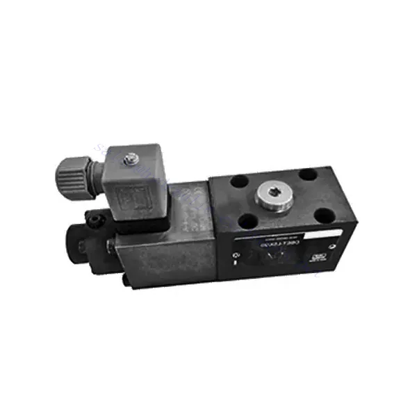
Zawór hydrauliczny proporcjonalny nadmiarowy ciśnienia serii DBET(E)
Jako jeden z producentów, dostawców i eksporterów produktów mechanicznych, oferujemy cylindry hydrauliczne i wiele innych produktów.
Prosimy o kontakt w celu uzyskania szczegółowych informacji.
Poczta:sales@hydraulic-cylinders.net
Producent dostawca eksporter siłowników hydraulicznych.
Zawór hydrauliczny proporcjonalny nadmiarowy ciśnienia serii DBET(E)
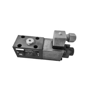
The DBET(E) series proportional pressure relief hydraulic valve is a cutting-edge component designed to deliver precise pressure control in hydraulic systems. With its advanced proportional control technology and exceptional performance, this valve optimizes system efficiency, enhances safety, and prolongs the lifespan of hydraulic equipment.
The DBET(E) series proportional pressure relief hydraulic valve is an indispensable component for achieving precise pressure control in hydraulic systems. With its proportional pressure regulation, enhanced efficiency, and equipment protection features, this valve optimizes system performance while ensuring the safety and longevity of hydraulic equipment. By following the recommended usage methods and maintenance guidelines, you can harness the full potential of the DBET(E) series proportional pressure relief hydraulic valve, maximizing the performance and reliability of your hydraulic system. Upgrade your hydraulic setup today and experience optimal pressure control with the DBET(E) series valve.
DBET(E) Series Proportional Pressure Relief Hydraulic Valve Key Characteristics:
- Sterowanie ciśnieniem proporcjonalnym:
- The DBET(E) series valve offers precise and proportional pressure relief, allowing for accurate and dynamic pressure regulation in hydraulic systems.
- It maintains a consistent pressure level against varying loads, ensuring optimal performance and preventing damage to hydraulic components.
- Zwiększona wydajność systemu:
- By providing proportional pressure control, this valve helps optimize system efficiency by reducing energy consumption and minimizing pressure fluctuations.
- It ensures that hydraulic equipment operates at the desired pressure, resulting in improved productivity and reduced operational costs.
- Safety and Equipment Protection:
- The DBET(E) Series Valve acts as a safety measure by limiting the pressure within the hydraulic system, preventing overloading and potential damage to equipment or operators.
- It safeguards sensitive components from excessive pressure, extending their lifespan and reducing the risk of system failures.
- Flexibility and Adaptability:
- This valve is available in different sizes and pressure ranges, allowing for compatibility with various hydraulic systems and applications.
- Its adaptable design makes it suitable for various industries, including manufacturing, construction, agriculture, and more.
DBET(E) Series Proportional Pressure Relief Hydraulic Valve Parameter:
| Płyn | Olej mineralny odpowiedni do uszczelnień NBR i FKM | |
| Ester fosforanowy do uszczelnień FKM | ||
| Zakres temperatur cieczy | ℃ | -30 do +80 (uszczelki NBR) |
| -20 to +80 (FKM seals) | ||
| Zakres lepkości | mm2/S | 15 to 380 |
| Stopień skażenia | Maximum permissible degree of fluid contamination: Class 9 and ISO4406 Class 20/18/15 | |
| Max. operating pressure (Port P) | bar | 350 |
| Maksymalne ciśnienie ustawienia | bar | 50; 100; 200; 315; 350 |
| Min. ustawialne ciśnienie | Zobacz krzywe charakterystyczne | |
| Min. ustawialne ciśnienie przy wartości polecenia 0 | =Minimalne ciśnienie do ustawienia | |
| Return pressure(Port T) | bar | Oddzielne i bezciśnieniowe do zbiornika |
| Maksymalny przepływ | l/min | 2 |
| Liniowość | ± 3.5 % of max. settable pressure | |
| Histereza | ± 1.5 % of max. settable pressure | |
| Powtarzalność | < ± 2 % of max. settable pressure | |
| Czas przełączania | SM | 30 to 150 (system dependent) |
DBET(E) Series Proportional Pressure Relief Hydraulic Valve Advantages:
• Direct, to restrict system pressure
• Installation face follows ISO 4401-03-02-0-05
• Pięć zakresów ciśnienia
• Accompanying electronic amplifier VT-2000 or plugin amplifier VT-SSPA1-…-L2X (separate order)
Usage Method Of DBET(E) Series Proportional Pressure Relief Hydraulic Valve :
- Ocena systemu:
- Assess the specific requirements of your hydraulic system, including the desired pressure range, maximum flow rate, and compatibility with existing components.
- Determine if the DBET(E) series valve suits your application based on its pressure control capabilities and compatibility with your system.
- Wybór zaworu:
- Choose the appropriate variant of the DBET(E) series valve based on your system parameters, required pressure range, and flow capacity.
- Należy wziąć pod uwagę maksymalne ciśnienie znamionowe, czas reakcji i warunki operacyjne.
- Instalacja:
- Dokładnie postępuj zgodnie z instrukcjami producenta dotyczącymi instalacji, aby zapewnić właściwe wyrównanie i bezpieczne mocowanie zaworu.
- Connect the valve to the hydraulic system, paying attention to the flow direction indicators and ensuring leak-free connections.
- Ustawienie ciśnienia:
- Adjust the pressure relief setting of the valve to match the desired pressure range for your application.
- This can typically be achieved through proportional control signals or adjustments on the valve itself, depending on the specific model.
Jak zamontować zawór hydrauliczny w ciągniku?
Adjusting a hydraulic flow control valve allows you to regulate the speed or flow rate of hydraulic fluid in a hydraulic system. By controlling the flow, you can optimize the performance of hydraulic cylinders, motors, or other hydraulic components. Here’s a step-by-step guide on how to adjust a hydraulic flow control valve:
- Identify the Flow Control Valve:
- Locate the flow control valve in your hydraulic system. It is typically installed in the hydraulic line leading to the component you want to control, such as a cylinder or motor.
- Understand the Valve Design:
- Familiarize yourself with the specific design of the flow control valve you are working with. Different valves may have varying adjustment mechanisms, such as a knob, screw, or handle.
- Determine the Desired Flow Rate:
- Assess the requirements of your hydraulic system and determine the desired flow rate or speed for the component you are controlling. This will guide you in adjusting the flow control valve accurately.
- Przygotuj system:
- Before making any adjustments, shut off the hydraulic system and relieve the pressure by moving the control levers back and forth or following the manufacturer’s recommended procedure.
- Locate the Adjustment Mechanism:
- Identify the adjustment mechanism on the flow control valve. It could be a knob, screw, or handle positioned on the valve body or adjacent to it.
- Adjust the Valve:
- If the valve has a knob or handle, turn it clockwise to decrease the flow rate or counterclockwise to increase the flow rate. If the valve has a screw, turn it clockwise to reduce the flow or counterclockwise to increase it.
- Wprowadź stopniowe zmiany:
- When adjusting the flow control valve, make small, incremental changes to avoid sudden or drastic variations in flow rate. This allows you to fine-tune the speed and achieve the desired performance.
- Observe the System:
- With each adjustment, observe the hydraulic system and the component being controlled. Pay attention to the speed or flow rate to see if it aligns with the desired outcome.
- Test and Refine:
- Operate the hydraulic system and the controlled component to test the effectiveness of your adjustments. If necessary, continue making incremental changes until the desired flow rate or speed is achieved.
- Zablokuj regulację:
- Once you have achieved the desired flow rate, secure the adjustment mechanism to prevent unintended changes. Some valves may have a locking nut or set screw that can be tightened to hold the adjustment in place.
- Monitor and Revisit:
- Regularly monitor the performance of the hydraulic system and the controlled component. If there are changes in the system or if the desired flow rate needs to be adjusted, revisit the flow control valve and repeat the adjustment process as needed.
Możliwości i pojemność fabryki:
(1) Montaż
Dysponujemy najwyższej klasy niezależną platformą badawczo-rozwojową. Warsztat produkcji siłowników hydraulicznych posiada cztery półautomatyczne linie montażowe siłowników podnoszących i jedną automatyczną linię montażową siłowników przechyłu, o projektowanej rocznej zdolności produkcyjnej 1 miliona sztuk. Specjalny warsztat cylindrów jest wyposażony w różne specyfikacje półautomatycznego systemu montażu czyszczącego o projektowanej rocznej zdolności produkcyjnej 200 000 i wyposażony w słynny sprzęt do obróbki CNC, centrum obróbcze, specjalny sprzęt do precyzyjnej obróbki cylindrów, robot spawalniczy, automatyczna maszyna czyszcząca, automatyczna maszyna do montażu cylindrów i automatyczna linia produkcyjna do malowania. Istniejący krytyczny sprzęt składa się z ponad 300 zestawów. Optymalna alokacja i efektywne wykorzystanie zasobów sprzętowych zapewniają wymagania dotyczące dokładności produktów i spełniają potrzeby wysokiej jakości produktów.


(2) Obróbka
Warsztat obróbki skrawaniem jest wyposażony w niestandardowe centrum tokarskie z pochyloną szyną, centrum obróbcze, szybkobieżną honownicę, robota spawalniczego i inny powiązany sprzęt, który może obsługiwać przetwarzanie rur cylindrycznych o maksymalnej średnicy wewnętrznej 400 mm i maksymalnej długości 6 metrów.

(3) Spawanie

(4) Malowanie i powlekanie
Z małymi i średnimi automatycznymi liniami do powlekania farbami na bazie wody, w celu osiągnięcia automatycznego załadunku i rozładunku robota oraz automatycznego natryskiwania, wydajność projektowa 4000 sztuk na zmianę;
Posiadamy również półautomatyczną linię do produkcji farb do dużych cylindrów napędzaną łańcuchem napędowym, o wydajności 60 skrzyń na zmianę.


(5) Testowanie
Dysponujemy najwyższej klasy urządzeniami kontrolnymi i stanowiskami testowymi, aby zapewnić, że wydajność cylindra spełnia wymagania.

Jesteśmy jednym z najlepszych producentów cylindrów hydraulicznych. Oferujemy kompleksową ofertę cylindrów hydraulicznych. Dostarczamy również… przekładnie rolnicze. Eksportowaliśmy nasze produkty do klientów na całym świecie i zdobyliśmy dobrą reputację dzięki najwyższej jakości produktów i usług posprzedażnych. Zapraszamy klientów w kraju i za granicą do kontaktu z nami w celu negocjacji biznesowych, wymiany informacji i współpracować z nami!
Siłownik hydrauliczny Zastosowanie:
