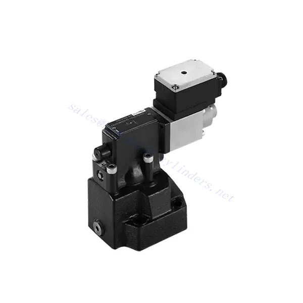
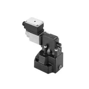
DRE(E) Series Proportional Pressure Reducing Valve
Jako jeden z producentów, dostawców i eksporterów produktów mechanicznych, oferujemy cylindry hydrauliczne i wiele innych produktów.
Prosimy o kontakt w celu uzyskania szczegółowych informacji.
Poczta:sales@hydraulic-cylinders.net
Producent dostawca eksporter siłowników hydraulicznych.
DRE(E) Series Proportional Pressure Reducing Valve
The DRE(E) series proportional pressure reducing valve is a state-of-the-art hydraulic component that delivers precise and reliable pressure control in various industrial applications. With its advanced features, exceptional performance, and robust construction, this valve offers a solution that optimizes system efficiency and enhances productivity.
The DRE(E) series proportional pressure reducing valve offers precise and reliable pressure control for hydraulic systems. With exceptional proportional control, pressure reduction function, high flow capacity, and fast response time, this valve provides accurate pressure regulation and safeguards downstream components. By following the recommended usage methods and maintenance guidelines, you can harness the full potential of this valve and achieve enhanced performance in your hydraulic applications. Upgrade your hydraulic system today with the DRE(E) series proportional pressure reducing valve and experience optimal pressure control with precision and reliability.
DRE(E) Series Proportional Pressure Reducing Valve Key Characteristics:
- Sterowanie proporcjonalne:
- The DRE(E) series valve boasts exceptional proportional control capabilities, enabling precise adjustment of pressure levels.
- This advanced control feature ensures accurate pressure regulation tailored to specific system requirements, promoting efficient and optimized performance.
- Pressure Reduction Function:
- Equipped with a pressure reduction function, this valve efficiently lowers the incoming pressure to a predefined setpoint.
- By accurately reducing the pressure, the valve protects downstream components, preventing damage and ensuring stable system operation.
- Wysoka przepustowość:
- The DRE(E) series valve is designed to handle high flow rates, making it suitable for applications that require substantial fluid volumes.
- Its high flow capacity enables efficient operation even in demanding industrial environments.
- Szybki czas reakcji:
- With an impressive response time, this valve allows for rapid adjustments to pressure changes within the system.
- The fast response ensures precise control, minimizing pressure fluctuations and promoting stable and consistent system performance.
DRE(E) Series Proportional Pressure Reducing Valve Parameter:
| Ogólny | |||||
| Płyn | Olej mineralny odpowiedni do uszczelnień NBR i FKM | ||||
| Ester fosforanowy do uszczelnień FKM | |||||
| Zakres temperatur cieczy | ℃ | -30 do +80 (uszczelnienie NBR) | |||
| -20 do +80 (uszczelnienie FKM) | |||||
| Zakres lepkości | mm2/S | 2.8 to 380 | |||
| Stopień skażenia | Maksymalny dopuszczalny stopień zanieczyszczenia płynem: Klasa 9. NAS 1638 lub 20/18/15, ISO4406 | ||||
| Maksymalne ciśnienie robocze | Port A,B | bar | 315 | ||
| Port Y | Oddzielne i bezciśnieniowe do zbiornika | ||||
| Maksymalne ciśnienie ustawienia | Port A | bar | 50; 100; 200; 315 | ||
| Min. ustawialne ciśnienie | Port A | W odniesieniu do przepływu (Q) patrz krzywe charakterystyczne | |||
| Pressure at current value 0 in port A | =Min. settable pressure (Refer to the characteristic curve ) | ||||
| Maksymalne ciśnienie bezpieczeństwa (regulowane bezstopniowo) | Ustawienie ciśnienia | Zakres ciśnienia poniżej maksymalnego ciśnienia bezpieczeństwa | |||
| 50 bar | 10-60+20 bar | ||||
| 100 bar | 10-120+20 bar | ||||
| 200 bar | 10-220+20 bar | ||||
| 315 bar | 10-340+20 bar | ||||
| Maksymalny stan bezpieczeństwa ustawienia ciśnienia | When rated pressure=50 bar, between 60~80 bar | ||||
| When rated pressure=100 bar, between 120~140 bar | |||||
| When rated pressure=200 bar, between 220~240 bar | |||||
| When rated pressure=315 bar, between 340~360 bar | |||||
| Rozmiar | 10 | 25 | 32 | ||
| Maksymalny przepływ | l/min | 80 | 200 | 300 | |
| Pilot flow-rate (for pilot valve) | l/min | 0,7 do 2 | |||
| Liniowość | ±3,5% | ||||
| Powtarzalność | <±2% | ||||
| Histereza | z shimmy | bez shimmy | |||
| ±2.5% Pmax( 200Hz, amplitude 200mAsss) | ±4.5% Pmax | ||||
| Czas przełączania | 100 to 300ms (undependent with the system) | ||||
| Dane elektryczne | |||||
| Moc | DC | ||||
| Min. prąd elektromagnesu | mama | 100 | |||
| Maksymalny prąd elektromagnesu | mama | 800 | |||
| Rezystancja cewki | 19.5Ω at 20℃, Max. warm value :28.8Ω | ||||
| Status pracy | Ciągły | ||||
| Max. ambient temperature range | +50℃ | ||||
| Połączenie elektryczne | Plug-in connector to DIN 43650/2+SL/PG11 | ||||
| Izolacja zgodna z DIN 40 050 | IP 65 | ||||
| Wzmacniacz | VT2000 | ||||
DRE(E) Series Proportional Pressure Reducing Valve Advantages:
• Stosowany do montażu na dolnej płycie pomocniczej
• Installation face follow DIN 24340 D and ISO 5781
• Stosowany w montażu bloków kanałów olejowych
• Cztery zakresy ciśnienia
• Konstrukcja zabezpieczająca przed najwyższym ciśnieniem (opcjonalnie)
• Pasujący wzmacniacz elektroniczny typu VT-2000 (należy zamówić osobno)
Usage Method Of DRE(E) Series Proportional Pressure Reducing Valve :
- Ocena systemu:
- Evaluate your hydraulic system’s requirements, considering flow rate, pressure range, and system dynamics.
- Determine whether the proportional pressure control offered by the DRE(E) series valve aligns with your system’s needs.
- Wybór zaworu:
- Select the appropriate variant of the DRE(E) series valve based on your system parameters and performance requirements.
- Aby zapewnić optymalną funkcjonalność, należy wziąć pod uwagę takie czynniki, jak przepustowość, zakres ciśnień i kompatybilność z innymi komponentami systemu.
- Instalacja:
- Należy dokładnie przestrzegać instrukcji producenta dotyczących instalacji, aby zapewnić właściwe umiejscowienie i bezpieczne mocowanie zaworu.
- Należy prawidłowo umiejscowić zawór w układzie hydraulicznym, biorąc pod uwagę takie czynniki, jak kierunek przepływu cieczy i dostępność w celu konserwacji.
- Ustawienie ciśnienia:
- Ustaw pożądany poziom ciśnienia poprzez regulację mechanizmu sterującego zaworu zgodnie z wytycznymi producenta.
- Upewnij się, że wartość zadana odpowiada konkretnym wymaganiom Twojego systemu.
How To Remove A Shower Valve Cartridge?
Removing a shower valve cartridge may vary depending on the specific model and manufacturer. However, here is a general step-by-step guide that can help you remove a shower valve cartridge:
- Turn off the Water Supply: Locate the main water shut-off valve for your shower and turn it off to cut off the water supply. This step is essential to prevent any water flow while you work on removing the cartridge.
- Remove the Shower Handle: Most shower handles have a screw or decorative cap at the base. Look for this screw or cap and remove it using a screwdriver or by gently prying it off. Once removed, take off the handle by pulling it straight out.
- Access the Cartridge: Depending on the type of shower valve you have, you may need to remove additional parts to access the cartridge. This can include a trim plate or escutcheon that covers the valve. Use a screwdriver to remove any screws holding these parts in place and gently pull them away.
- Remove the Retaining Clip or Nut: Look for a retaining clip or nut that holds the cartridge in place. This clip or nut is usually located on the top of the cartridge and secures it to the valve body. Use pliers or an adjustable wrench to loosen and remove the clip or nut.
- Remove the Cartridge: Once the retaining clip or nut is removed, you can proceed to pull out the cartridge. Grip the cartridge firmly and pull it straight out of the valve body. If it is stuck, you may need to wiggle it gently or use a cartridge removal tool specific to your shower valve model.
- Wyczyść i sprawdź: With the cartridge removed, take a moment to clean any debris or sediment from the valve body using a soft brush or cloth. Inspect the cartridge for any signs of damage or wear. If necessary, replace the cartridge with a new one that matches the model and make of your shower valve.
- Reassemble and Test: Once you have cleaned or replaced the cartridge, reassemble the shower valve by following the steps in reverse order. Make sure all parts are securely in place. Turn on the water supply and test the shower to ensure there are no leaks and that the new cartridge is functioning properly.
Możliwości i pojemność fabryki:
(1) Montaż
Dysponujemy najwyższej klasy niezależną platformą badawczo-rozwojową. Warsztat produkcji siłowników hydraulicznych posiada cztery półautomatyczne linie montażowe siłowników podnoszących i jedną automatyczną linię montażową siłowników przechyłu, o projektowanej rocznej zdolności produkcyjnej 1 miliona sztuk. Specjalny warsztat cylindrów jest wyposażony w różne specyfikacje półautomatycznego systemu montażu czyszczącego o projektowanej rocznej zdolności produkcyjnej 200 000 i wyposażony w słynny sprzęt do obróbki CNC, centrum obróbcze, specjalny sprzęt do precyzyjnej obróbki cylindrów, robot spawalniczy, automatyczna maszyna czyszcząca, automatyczna maszyna do montażu cylindrów i automatyczna linia produkcyjna do malowania. Istniejący krytyczny sprzęt składa się z ponad 300 zestawów. Optymalna alokacja i efektywne wykorzystanie zasobów sprzętowych zapewniają wymagania dotyczące dokładności produktów i spełniają potrzeby wysokiej jakości produktów.


(2) Obróbka
Warsztat obróbki skrawaniem jest wyposażony w niestandardowe centrum tokarskie z pochyloną szyną, centrum obróbcze, szybkobieżną honownicę, robota spawalniczego i inny powiązany sprzęt, który może obsługiwać przetwarzanie rur cylindrycznych o maksymalnej średnicy wewnętrznej 400 mm i maksymalnej długości 6 metrów.

(3) Spawanie

(4) Malowanie i powlekanie
Z małymi i średnimi automatycznymi liniami do powlekania farbami na bazie wody, w celu osiągnięcia automatycznego załadunku i rozładunku robota oraz automatycznego natryskiwania, wydajność projektowa 4000 sztuk na zmianę;
Posiadamy również półautomatyczną linię do produkcji farb do dużych cylindrów napędzaną łańcuchem napędowym, o wydajności 60 skrzyń na zmianę.


(5) Testowanie
Dysponujemy najwyższej klasy urządzeniami kontrolnymi i stanowiskami testowymi, aby zapewnić, że wydajność cylindra spełnia wymagania.

Jesteśmy jednym z najlepszych producentów cylindrów hydraulicznych. Oferujemy kompleksową ofertę cylindrów hydraulicznych. Dostarczamy również… przekładnie rolnicze. Eksportowaliśmy nasze produkty do klientów na całym świecie i zdobyliśmy dobrą reputację dzięki najwyższej jakości produktów i usług posprzedażnych. Zapraszamy klientów w kraju i za granicą do kontaktu z nami w celu negocjacji biznesowych, wymiany informacji i współpracować z nami!
Siłownik hydrauliczny Zastosowanie:
