
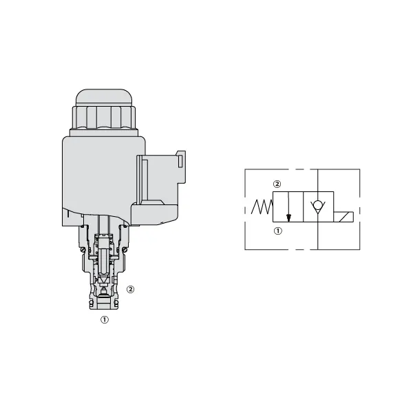
KSE66-C0820 Zawór elektromagnetyczny kierunkowy
Jako jeden z producentów, dostawców i eksporterów produktów mechanicznych, oferujemy cylindry hydrauliczne i wiele innych produktów.
Prosimy o kontakt w celu uzyskania szczegółowych informacji.
Poczta:sales@hydraulic-cylinders.net
Producent dostawca eksporter siłowników hydraulicznych.
KSE66-C0820 Zawór elektromagnetyczny kierunkowy
Elektrozawór kierunkowy kse66-c0820 to innowacyjny i niezawodny element zaprojektowany z myślą o wyniesieniu systemów sterowania przepływem cieczy na nowy poziom. Dzięki zaawansowanym funkcjom i precyzyjnym możliwościom sterowania, zawór ten stanowi idealne rozwiązanie dla różnorodnych zastosowań przemysłowych. Niezależnie od tego, czy chodzi o produkcję, automatyzację, czy inne procesy sterowania przepływem cieczy, elektrozawór kierunkowy kse66-c0820 zapewnia płynną pracę i wyjątkową wydajność.
Elektrozawór kierunkowy KSE66-C0820 oferuje wyjątkowe możliwości sterowania przepływem cieczy, gwarantując optymalną wydajność w różnych zastosowaniach przemysłowych. Dzięki wysokiej jakości konstrukcji, precyzyjnemu sterowaniu, kompaktowej konstrukcji i szybkiemu czasowi reakcji, zawór ten stanowi niezawodny wybór do usprawnienia systemów sterowania przepływem cieczy. Przestrzegając prawidłowej metody użytkowania i regularnie przeprowadzając konserwację, można zmaksymalizować potencjał elektrozaworu kierunkowego KSE66-C0820 i osiągnąć doskonałą wydajność sterowania przepływem cieczy w swoich procesach. Zmodernizuj swój system sterowania przepływem cieczy już dziś, korzystając z niezawodności i wydajności elektrozaworu kierunkowego KSE66-C0820.
Charakterystyka zaworu elektromagnetycznego KSE66-C0820:
- Wysokiej jakości konstrukcja: Elektromagnetyczny zawór kierunkowy KSE66-C0820 został wykonany z najwyższej jakości materiałów, co zapewnia wyjątkową trwałość i długotrwałą wydajność. Został zaprojektowany tak, aby wytrzymać trudne warunki pracy, w tym wysokie ciśnienia i trudne warunki środowiskowe, bez uszczerbku dla jego funkcjonalności.
- Precyzyjna kontrola płynów: Dzięki najnowocześniejszej konstrukcji elektromagnetyczny zawór kierunkowy KSE66-C0820 zapewnia precyzyjną kontrolę przepływu i kierunku cieczy. Umożliwia precyzyjną regulację, zapewniając optymalną wydajność i efektywność w różnych zastosowaniach.
- Kompaktowy i lekki: Ten zawór został zaprojektowany tak, aby był kompaktowy i lekki, co ułatwia integrację z różnymi systemami sterowania przepływem cieczy. Jego opływowa konstrukcja zapewnia efektywne wykorzystanie przestrzeni przy jednoczesnym zachowaniu doskonałej wydajności.
- Szybki czas reakcji: Elektromagnetyczny zawór kierunkowy KSE66-C0820 charakteryzuje się szybkim czasem reakcji, umożliwiając szybkie i niezawodne przełączanie między różnymi ścieżkami przepływu. Zapewnia to płynną pracę i poprawia wydajność systemu, nawet w dynamicznych i wymagających dużej szybkości działania aplikacjach.
Parametry zaworu elektromagnetycznego KSE66-C0820:
| Ciśnienie znamionowe | 350 barów (5000 psi) |
| Przepływ szczytowy | 40 l/min (10 gpm) |
| Płyn | Olej mineralny – odpowiedni do uszczelnień Buna N lub fluorowęglowodorowych |
| Ester fosforanowy – odpowiedni do uszczelnień fluorowęglowych | |
| Zakres temperatury płynu ℃ | – 30 do 80 (uszczelki Buna N) |
| – 20 do 80 (uszczelki fluorowęglowe) | |
| Zakres lepkości | 7,4 do 420 mm2/S |
| Stopień zanieczyszczenia płynem | Minimalny poziom zanieczyszczenia to ISO4406 poziom 18/16/13, a w celu wydłużenia żywotności zaleca się poziom 15/13/11 |
| Wyciek wewnętrzny | ≦ 5 dni na minutę |
| Wgłębienie | VC08-2 |
| Waga | 0,33 kg |
| Obciążenie cewki | Ciągły od 85% do 115% napięcia znamionowego |
| Początkowy pobór prądu cewki przy 20℃ | 1,5 A przy 12 V DC; 0,8 A przy 24 V DC |
| Minimalne napięcie wciągania | 85% nominalny przy 350 barach |
Zalety elektrozaworu kierunkowego KSE66-C0820:
• Cewka o pracy ciągłej
• Wkłady są wymienne pod względem napięcia
• Opcjonalne wodoodporne cewki elektryczne o klasie ochrony IP69K
• Wspólna wnęka przemysłowa
• Utwardzone części zapewniające długą żywotność
Sposób użycia elektrozaworu kierunkowego KSE66-C0820:
- Ocena systemu: Oceń wymagania układu sterowania przepływem, w tym wartości ciśnienia, natężenia przepływu i potrzeby sterowania kierunkowego. Upewnij się, że elektrozawór kierunkowy KSE66-C0820 jest kompatybilny z Twoim konkretnym zastosowaniem.
- Montaż i podłączenie: Wybierz odpowiednią metodę montażu, biorąc pod uwagę konfigurację systemu i dostępną przestrzeń. Zamontuj zawór solidnie, dopasowując go do przewodów cieczowych. Podłącz zawór za pomocą kompatybilnych złączek i łączników, zapewniając szczelne i szczelne połączenia.
- Podłączenie elektryczne: Podłącz elektrozawór zaworu do odpowiedniego źródła zasilania, postępując zgodnie z instrukcjami producenta. Upewnij się, że okablowanie jest prawidłowe i zachowaj środki ostrożności podczas podłączania elektrycznego.
- Testowanie i kalibracja: Stopniowo wprowadzaj przepływ cieczy do układu i monitoruj działanie zaworu. Przetestuj różne warunki pracy, takie jak zmiany ciśnienia i przepływu, i w razie potrzeby skalibruj ustawienia zaworu, aby uzyskać optymalną kontrolę i funkcjonalność układu.
Jak wymienić wkład zaworowy w kranie Delta?
Aby wymienić wkład zaworowy w baterii Delta, należy postępować zgodnie z poniższą instrukcją krok po kroku:
- Zbierz niezbędne narzędzia: Będziesz potrzebować zestawu kluczy imbusowych, pary szczypiec (regulowanych lub z rowkiem), śrubokręta (krzyżakowego lub płaskiego) i zamiennego wkładu zaworowego Delta, odpowiedniego do modelu twojego kranu.
- Wyłącz dopływ wody: Znajdź zawory odcinające pod zlewem lub przy głównym dopływie wody i zamknij dopływ wody do kranu. Otwórz kurki kranów, aby spuścić pozostałą wodę z przewodów i upewnij się, że dopływ wody jest całkowicie zamknięty.
- Zdemontuj uchwyt kranu: Baterie Delta mają różne rodzaje uchwytów, takie jak uchwyt jednouchwytowy lub dwuuchwytowy. W przypadku uchwytu jednouchwytowego należy zlokalizować śrubę ustalającą na uchwycie, zazwyczaj znajdującą się pod ozdobną nasadką lub przyciskiem. Za pomocą klucza imbusowego odkręcić śrubę ustalającą i zdjąć uchwyt. W przypadku baterii dwuuchwytowej, należy zdjąć uchwyt, odkręcając ozdobną nasadkę lub śrubę uchwytu.
- Wyjmij wkład: Po zdjęciu uchwytu zobaczysz wkład. Użyj szczypiec, aby poluzować i zdjąć nakrętkę wkładu, obracając ją w kierunku przeciwnym do ruchu wskazówek zegara. Jeśli jest to oporne, możesz użyć narzędzia do wyjmowania wkładu, aby zwiększyć siłę nacisku. Wyciągnij wkład prosto z korpusu baterii.
- Zainstaluj wkład zamienny: Weź nowy wkład zaworu Delta i wyrównaj go z korpusem baterii, upewniając się, że wszystkie wypustki i nacięcia pasują do siebie. Delikatnie wsuń wkład w korpus baterii, aż będzie dobrze przylegał.
- Ponowny montaż kranu: Po zamontowaniu nowego wkładu, złóż baterię w odwrotnej kolejności. Nasuń nakrętkę wkładu z powrotem na korpus zaworu i dokręć ją szczypcami. Upewnij się, że jest dobrze dokręcona, ale unikaj nadmiernego dokręcania. Zamontuj ponownie uchwyt baterii i dokręć śrubę ustalającą lub śrubę uchwytu.
- Włącz dopływ wody: Powoli odkręć dopływ wody za pomocą zaworów odcinających lub głównego dopływu wody. Sprawdź, czy nie ma wycieków wokół kranu i uchwytu. W razie potrzeby dokręć nakrętkę kartusza lub uchwyt mocniej.
- Przetestuj kran: Po przywróceniu dopływu wody sprawdź działanie kranu, odkręcając pokrętła i sprawdzając, czy działa płynnie. Upewnij się, że ciepła i zimna woda płyną prawidłowo i dostosuj temperaturę do swoich potrzeb.
Możliwości i pojemność fabryki:
(1) Montaż
Dysponujemy najwyższej klasy niezależną platformą badawczo-rozwojową. Warsztat produkcji siłowników hydraulicznych posiada cztery półautomatyczne linie montażowe siłowników podnoszących i jedną automatyczną linię montażową siłowników przechyłu, o projektowanej rocznej zdolności produkcyjnej 1 miliona sztuk. Specjalny warsztat cylindrów jest wyposażony w różne specyfikacje półautomatycznego systemu montażu czyszczącego o projektowanej rocznej zdolności produkcyjnej 200 000 i wyposażony w słynny sprzęt do obróbki CNC, centrum obróbcze, specjalny sprzęt do precyzyjnej obróbki cylindrów, robot spawalniczy, automatyczna maszyna czyszcząca, automatyczna maszyna do montażu cylindrów i automatyczna linia produkcyjna do malowania. Istniejący krytyczny sprzęt składa się z ponad 300 zestawów. Optymalna alokacja i efektywne wykorzystanie zasobów sprzętowych zapewniają wymagania dotyczące dokładności produktów i spełniają potrzeby wysokiej jakości produktów.


(2) Obróbka
Warsztat obróbki skrawaniem jest wyposażony w niestandardowe centrum tokarskie z pochyloną szyną, centrum obróbcze, szybkobieżną honownicę, robota spawalniczego i inny powiązany sprzęt, który może obsługiwać przetwarzanie rur cylindrycznych o maksymalnej średnicy wewnętrznej 400 mm i maksymalnej długości 6 metrów.

(3) Spawanie

(4) Malowanie i powlekanie
Z małymi i średnimi automatycznymi liniami do powlekania farbami na bazie wody, w celu osiągnięcia automatycznego załadunku i rozładunku robota oraz automatycznego natryskiwania, wydajność projektowa 4000 sztuk na zmianę;
Posiadamy również półautomatyczną linię do produkcji farb do dużych cylindrów napędzaną łańcuchem napędowym, o wydajności 60 skrzyń na zmianę.


(5) Testowanie
Dysponujemy najwyższej klasy urządzeniami kontrolnymi i stanowiskami testowymi, aby zapewnić, że wydajność cylindra spełnia wymagania.

Jesteśmy jednym z najlepszych producentów cylindrów hydraulicznych. Oferujemy kompleksową ofertę cylindrów hydraulicznych. Dostarczamy również… przekładnie rolnicze. Eksportowaliśmy nasze produkty do klientów na całym świecie i zdobyliśmy dobrą reputację dzięki najwyższej jakości produktów i usług posprzedażnych. Zapraszamy klientów w kraju i za granicą do kontaktu z nami w celu negocjacji biznesowych, wymiany informacji i współpracować z nami!
Siłownik hydrauliczny Zastosowanie:
