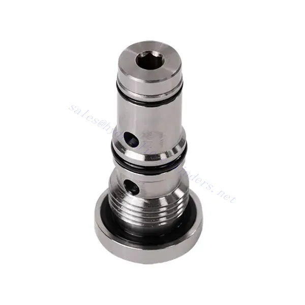
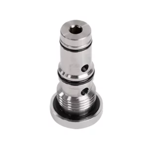
KSF Series Shuttle Hydraulic Valve
Jako jeden z producentów, dostawców i eksporterów produktów mechanicznych, oferujemy cylindry hydrauliczne i wiele innych produktów.
Prosimy o kontakt w celu uzyskania szczegółowych informacji.
Poczta:sales@hydraulic-cylinders.net
Producent dostawca eksporter siłowników hydraulicznych.
KSF Series Shuttle Hydraulic Valve
The KSF series shuttle hydraulic valve is a high-performance component designed to enhance fluid flow control in hydraulic systems. With its advanced design and robust construction, this valve offers precise and reliable operation, ensuring optimal system performance.
The KSF series shuttle hydraulic valve is an exceptional solution for fluid flow control in hydraulic systems. With its shuttle valve functionality, robust construction, high flow capacity, and compact design, this valve optimizes performance and ensures efficient utilization of hydraulic power. By following the recommended usage methods and maintenance practices, the KSF series shuttle hydraulic valve delivers reliable operation and extends the lifespan of hydraulic systems. Upgrade your hydraulic system with the KSF series shuttle hydraulic valve and experience enhanced fluid flow control for improved overall system performance.
KSF Series Shuttle Hydraulic Valve Key Characteristics:
- Shuttle Valve Functionality:
- The KSF series valve incorporates a shuttle valve design to divert hydraulic fluid flow between two circuits.
- It enables the selection of the circuit with higher pressure, ensuring efficient utilization of hydraulic power and preventing pressure imbalances.
- Solidna konstrukcja:
- Built with durable materials, the KSF series shuttle hydraulic valve is designed to withstand high-pressure environments and demanding operating conditions.
- Its robust construction ensures longevity and reliability, minimizing downtime and maintenance costs.
- Wysoka przepustowość:
- The KSF series valve offers a high flow capacity, allowing for efficient transfer of hydraulic fluid between circuits.
- It minimizes pressure drops, ensuring maximum power delivery and system performance.
- Kompaktowa i wszechstronna konstrukcja:
- The valve’s compact design makes it suitable for installations with limited space or weight constraints.
- Its versatility allows easy integration into various hydraulic systems, including industrial machinery, mobile equipment, and power units.
KSF Series Shuttle Hydraulic Valve Parameter:
| Rozmiar | NG6 | NG10 | |
| Zakres temperatur cieczy | ℃ | -30 do +80 (uszczelki NBR) | |
| -20 do +80 (uszczelki FKM) | |||
| Zakres lepkości | mm2/S | Zalecenie 30~80, pozwolenie 20~380 | |
| Maksymalne ciśnienie robocze | bar | 350 | |
| Maksymalny przepływ | l/min | 40 | 60 |
| Waga | kg | 0.5 | 0.8 |
| Płyn | Olej mineralny odpowiedni do uszczelnień NBR i FKM | ||
| Ester fosforanowy do uszczelnień FKM | |||
| Stopień skażenia | Maksymalny dopuszczalny stopień zanieczyszczenia płynem: Klasa 9. NAS 1638 lub 20/18/15, ISO4406 | ||
KSF Series Shuttle Hydraulic Valve Advantages:
• Seal without leakage
• Cartridge structure for oil block installation
Usage Method Of KSF Series Shuttle Hydraulic Valve:
- Analiza systemu:
- Before installation, perform a comprehensive hydraulic system analysis to determine specific requirements and operating parameters.
- Consider factors such as flow rates, pressure ratings, and compatibility with the KSF series shuttle hydraulic valve.
- Wybór zaworu:
- Choose the appropriate KSF series valve variant based on the system’s requirements and specifications.
- Należy wziąć pod uwagę takie czynniki, jak przepustowość, ciśnienie znamionowe i kompatybilność z innymi komponentami systemu.
- Instalacja:
- Follow the manufacturer’s instructions for properly installing the KSF series shuttle hydraulic Valve in the hydraulic system.
- Ensure a secure fit, proper alignment with the fluid flow path, and adequate sealing to prevent leaks.
- Circuit Connection:
- Connect the inlet and outlet ports of the valve to the corresponding circuits that require fluid diversion.
- Ensure proper identification and connection of the high-pressure circuit and low-pressure circuit.
Jak działa zawór sterujący przepływem hydraulicznym?
Zawór sterujący przepływem hydraulicznym to urządzenie służące do regulacji i sterowania prędkością płynu hydraulicznego w układzie hydraulicznym. Umożliwia operatorowi regulację natężenia przepływu płynu, zapobiegając w ten sposób zmniejszeniu prędkości siłowników hydraulicznych lub kontrolując szybkość przesyłu energii. Oto wyjaśnienie działania zaworu sterującego przepływem hydraulicznym:
- Struktura zaworu:
- Zawór sterujący przepływem hydraulicznym zazwyczaj składa się z korpusu zaworu z portami wlotowymi i wylotowymi, ruchomego suwaka lub grzybka i mechanizmu uruchamiającego.
- Korpus zaworu zawiera wewnętrzne kanały i komory, które kontrolują przepływ płynu hydraulicznego.
- Drogi przepływu cieczy:
- Zawór sterujący przepływem ma otwór wlotowy, który łączy się ze źródłem zasilania hydraulicznego, na przykład pompą, oraz otwór wylotowy, który łączy się z siłownikiem hydraulicznym lub innym elementem.
- Zawór zapewnia różne ścieżki przepływu cieczy, umożliwiając jej kontrolowanie i regulację.
- Szpula lub grzybek:
- W korpusie zaworu znajduje się ruchomy suwak lub grzybek, który reguluje przepływ płynu hydraulicznego.
- Szpula może przesuwać się w korpusie zaworu, natomiast grzybek może poruszać się liniowo lub obracać, otwierając lub zamykając określone kanały.
- Mechanizm uruchamiający:
- Zawory sterujące przepływem hydraulicznym mogą być uruchamiane ręcznie, elektrycznie lub innymi sposobami, zależnie od konkretnych wymagań konstrukcyjnych i zastosowania.
- Sterowanie ręczne polega na ustawieniu uchwytu, pokrętła lub dźwigni w celu odpowiedniego ustawienia szpuli lub grzybka.
- Siłownik elektryczny wykorzystuje elektromagnesy, które odbierają sygnały elektryczne w celu przesunięcia szpuli lub grzybka, co umożliwia zdalne sterowanie i automatyzację.
- Pozycje zaworów:
- Zawór sterujący przepływem hydraulicznym zwykle ma wiele pozycji, które może przyjąć suwak lub grzybek, z których każda odpowiada określonej szybkości przepływu.
- Zawór może mieć szereg wstępnie ustawionych pozycji lub umożliwiać ciągłą regulację w celu precyzyjnego dostrojenia natężenia przepływu.
- Gdy szpula lub grzybek się przesuwa, ustawia się on względem określonych kanałów, otwierając je lub zamykając, aby kontrolować przepływ cieczy.
- Regulacja przepływu:
- Regulując położenie suwaka lub grzybka, operator może kontrolować wielkość kanałów przepływowych, regulując w ten sposób natężenie przepływu płynu hydraulicznego.
- Gdy kanały są całkowicie otwarte, płyn przepływa swobodnie, co pozwala na maksymalną szybkość przepływu.
- Częściowe zamknięcie kanałów ogranicza przepływ, zmniejszając jego natężenie i kontrolując prędkość siłowników hydraulicznych.
- Kompensacja ciśnienia:
- Niektóre zawory sterujące przepływem hydraulicznym zawierają mechanizmy kompensacji ciśnienia, które utrzymują stałą szybkość przepływu pomimo zmian ciśnienia w układzie.
- Mechanizmy te zapewniają utrzymanie pożądanej szybkości przepływu nawet wtedy, gdy w układzie występują wahania obciążenia lub ciśnienia.
Możliwości i pojemność fabryki:
(1) Montaż
Dysponujemy najwyższej klasy niezależną platformą badawczo-rozwojową. Warsztat produkcji siłowników hydraulicznych posiada cztery półautomatyczne linie montażowe siłowników podnoszących i jedną automatyczną linię montażową siłowników przechyłu, o projektowanej rocznej zdolności produkcyjnej 1 miliona sztuk. Specjalny warsztat cylindrów jest wyposażony w różne specyfikacje półautomatycznego systemu montażu czyszczącego o projektowanej rocznej zdolności produkcyjnej 200 000 i wyposażony w słynny sprzęt do obróbki CNC, centrum obróbcze, specjalny sprzęt do precyzyjnej obróbki cylindrów, robot spawalniczy, automatyczna maszyna czyszcząca, automatyczna maszyna do montażu cylindrów i automatyczna linia produkcyjna do malowania. Istniejący krytyczny sprzęt składa się z ponad 300 zestawów. Optymalna alokacja i efektywne wykorzystanie zasobów sprzętowych zapewniają wymagania dotyczące dokładności produktów i spełniają potrzeby wysokiej jakości produktów.


(2) Obróbka
Warsztat obróbki skrawaniem jest wyposażony w niestandardowe centrum tokarskie z pochyloną szyną, centrum obróbcze, szybkobieżną honownicę, robota spawalniczego i inny powiązany sprzęt, który może obsługiwać przetwarzanie rur cylindrycznych o maksymalnej średnicy wewnętrznej 400 mm i maksymalnej długości 6 metrów.

(3) Spawanie

(4) Malowanie i powlekanie
Z małymi i średnimi automatycznymi liniami do powlekania farbami na bazie wody, w celu osiągnięcia automatycznego załadunku i rozładunku robota oraz automatycznego natryskiwania, wydajność projektowa 4000 sztuk na zmianę;
Posiadamy również półautomatyczną linię do produkcji farb do dużych cylindrów napędzaną łańcuchem napędowym, o wydajności 60 skrzyń na zmianę.


(5) Testowanie
Dysponujemy najwyższej klasy urządzeniami kontrolnymi i stanowiskami testowymi, aby zapewnić, że wydajność cylindra spełnia wymagania.

Jesteśmy jednym z najlepszych producentów cylindrów hydraulicznych. Oferujemy kompleksową ofertę cylindrów hydraulicznych. Dostarczamy również… przekładnie rolnicze. Eksportowaliśmy nasze produkty do klientów na całym świecie i zdobyliśmy dobrą reputację dzięki najwyższej jakości produktów i usług posprzedażnych. Zapraszamy klientów w kraju i za granicą do kontaktu z nami w celu negocjacji biznesowych, wymiany informacji i współpracować z nami!
Siłownik hydrauliczny Zastosowanie:
