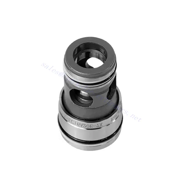
L-LC Series Pressure Control Function Hydraulic Valve
Jako jeden z producentów, dostawców i eksporterów produktów mechanicznych, oferujemy cylindry hydrauliczne i wiele innych produktów.
Prosimy o kontakt w celu uzyskania szczegółowych informacji.
Poczta:sales@hydraulic-cylinders.net
Producent dostawca eksporter siłowników hydraulicznych.
L-LC Series Pressure Control Function Hydraulic Valve
The L-LC series pressure control function hydraulic valve is an exceptional hydraulic component designed to provide precise pressure control in a variety of applications. With its advanced features and robust construction, this valve empowers hydraulic systems to achieve optimal performance and efficiency.
The L-LC series pressure control function hydraulic valve is a game-changer for hydraulic systems, offering precise pressure control, versatility, and durability. By following the recommended usage methods and maintenance guidelines, you can harness the full potential of the L-LC series valve and experience enhanced control, safety, and efficiency in your hydraulic applications. Upgrade your hydraulic system today and unlock the advantages of precision and control with the L-LC series pressure control function hydraulic valve.
L-LC Series Pressure Control Function Hydraulic Valve Key Characteristics:
- Pressure Control Function:
- The L-LC series valve incorporates a sophisticated pressure control function, allowing precise hydraulic pressure regulation within the system.
- This characteristic ensures consistent and reliable pressure management, enhancing system performance, improved safety, and reduced energy consumption.
- Versatile Configuration Options:
- This valve is available in various configurations, including 2-way and 3-way options, ensuring compatibility with different hydraulic system requirements.
- The 2-way configuration facilitates on/off pressure control, while the 3-way design enables more complex control functions, such as pressure relief or bypass.
- Wysokiej jakości konstrukcja:
- The L-LC series valve is meticulously engineered with high-quality materials and precision manufacturing techniques to ensure durability and longevity.
- Its robust construction allows it to withstand harsh operating conditions, including high pressures, temperature variations, and contaminant exposure.
- Szybki czas reakcji:
- This valve boasts an impressive response time, enabling rapid adjustments to pressure changes within the hydraulic system.
- The fast response time ensures quick and precise control, optimizing system performance and minimizing the risk of pressure fluctuations.
L-LC Series Pressure Control Function Hydraulic Valve Parameter:
| Technical data | ||||||||
| Płyn | Olej mineralny odpowiedni do uszczelnień NBR i FKM | |||||||
| Ester fosforanowy do uszczelnień FKM | ||||||||
| Zakres temperatur cieczy | ℃ | -30 do +80 (uszczelnienie NBR) | ||||||
| -20 do +80 (uszczelnienie FKM) | ||||||||
| Zakres lepkości | mm2/S | 2.8 to 380 | ||||||
| Stopień skażenia | Maximum permissible degree of fluid contamination: Class 9. NAS 1638 or 20/18/15 , ISO4406 | |||||||
| Two-way cartridge valves | ||||||||
| Max. operating pressure -Port A and B | bar | 420 | ||||||
| Max. flow-rate((recommendation) | Rozmiar | 16 | 25 | 32 | 40 | 50 | 63 | |
| Poppet valve cartridge “E”and”A” | l/min | 300 | 450 | 600 | 1000 | 1600 | 2500 | |
| Spool valve cartridge “D”and”B” | l/min | 175 | 300 | 450 | 700 | 1400 | 1750 | |
L-LC Series Pressure Control Function Hydraulic Valve Advantages:
• Optional pressure adjustment control cover, and integrate other functions
• Multiple pressure levels are available
Usage Method Of L-LC Series Pressure Control Function Hydraulic Valve:
- Ocena systemu:
- Evaluate your hydraulic system and identify the specific pressure control requirements.
- Determine whether the L-LC series valve suits your system based on pressure range, flow rates, and compatibility with your application.
- Wybór zaworu:
- Select the appropriate variant of the L-LC series valve based on your system parameters and pressure control needs.
- Consider pressure rating, flow capacity, response time, and compatibility with your specific application.
- Instalacja:
- Follow the manufacturer’s installation instructions carefully to ensure proper alignment and secure valve mounting.
- Use compatible hydraulic fittings, adapters, and seals to establish leak-free connections. Tighten the connections adequately, avoiding overtightening that could damage the valve or fittings.
- Pressure Calibration:
- Calibrate the L-LC series valve to the desired pressure range using appropriate pressure measurement equipment and adjusting mechanisms.
- Follow the manufacturer’s guidelines for pressure calibration procedures and ensure that the valve operates within the specified pressure limits.
How To Install A Hydraulic Flow Control Valve?
To install a hydraulic flow control valve, follow these step-by-step instructions:
- Zidentyfikuj zawór: Determine the specific type of hydraulic flow control valve you work with. Various types are available, including needle valves, orifice valves, and adjustable flow control valves. Ensure the valve is suitable for your application and compatible with your hydraulic system.
- Gather the Required Tools and Materials: Collect the necessary tools and materials, including appropriate hydraulic fittings, adapters, hoses, wrenches, and Teflon tape (thread sealant). Refer to the manufacturer’s instructions for any specific tools or components needed.
- Prepare the Hydraulic System: Shut down the hydraulic system and relieve pressure by activating the relief valve or retracting hydraulic cylinders. This step is crucial for safety and prevents accidental movement or hydraulic fluid release.
- Identify the Flow Direction: Determine the flow direction in your hydraulic system. Typically, the flow direction is indicated by arrows on the hydraulic components. Ensure that you understand the correct flow direction before proceeding.
- Determine the Installation Point: Identify the optimal location to install the hydraulic flow control valve in your hydraulic system. Consider factors such as accessibility, proximity to the actuator or hydraulic component, and ease of operation. Ensure there is enough space for the valve to be mounted securely.
- Mount the Valve: Securely mount the hydraulic flow control valve in the chosen location using appropriate brackets or clamps. Ensure the valve is positioned correctly, aligning the inlet and outlet ports with the flow direction. Follow the manufacturer’s instructions for the specific mounting requirements of your valve.
- Connect the Inlet and Outlet Ports: Attach hydraulic hoses or tubing to the inlet and outlet ports of the hydraulic flow control valve. Use suitable hydraulic fittings and adapters to create a leak-free connection. Apply Teflon tape or thread sealant to the male threads of the fittings to ensure a secure and sealed connection. Tighten the connections using wrenches to avoid leaks but be careful not to overtighten.
- Adjust the Flow Rate: Depending on the type of flow control valve, you may need to adjust the flow rate. Some valves have adjustable knobs or screws that allow you to fine-tune the flow rate. Follow the manufacturer’s instructions to set the desired flow rate.
- Przetestuj system: Once the hydraulic flow control valve is installed, slowly restore hydraulic system pressure. Test the system to ensure that the valve is functioning correctly. Observe the flow rate and verify that the valve is controlling the flow as intended. Make any necessary adjustments to achieve the desired flow rate.
- Monitor and Maintain: Regularly inspect the hydraulic flow control valve for any signs of leakage, damage, or reduced performance. Clean the valve and surrounding area to remove dirt and debris that may affect its operation. Follow the manufacturer’s recommended maintenance schedule and guidelines to ensure optimal performance and longevity.
Możliwości i pojemność fabryki:
(1) Montaż
Dysponujemy najwyższej klasy niezależną platformą badawczo-rozwojową. Warsztat produkcji siłowników hydraulicznych posiada cztery półautomatyczne linie montażowe siłowników podnoszących i jedną automatyczną linię montażową siłowników przechyłu, o projektowanej rocznej zdolności produkcyjnej 1 miliona sztuk. Specjalny warsztat cylindrów jest wyposażony w różne specyfikacje półautomatycznego systemu montażu czyszczącego o projektowanej rocznej zdolności produkcyjnej 200 000 i wyposażony w słynny sprzęt do obróbki CNC, centrum obróbcze, specjalny sprzęt do precyzyjnej obróbki cylindrów, robot spawalniczy, automatyczna maszyna czyszcząca, automatyczna maszyna do montażu cylindrów i automatyczna linia produkcyjna do malowania. Istniejący krytyczny sprzęt składa się z ponad 300 zestawów. Optymalna alokacja i efektywne wykorzystanie zasobów sprzętowych zapewniają wymagania dotyczące dokładności produktów i spełniają potrzeby wysokiej jakości produktów.


(2) Obróbka
Warsztat obróbki skrawaniem jest wyposażony w niestandardowe centrum tokarskie z pochyloną szyną, centrum obróbcze, szybkobieżną honownicę, robota spawalniczego i inny powiązany sprzęt, który może obsługiwać przetwarzanie rur cylindrycznych o maksymalnej średnicy wewnętrznej 400 mm i maksymalnej długości 6 metrów.

(3) Spawanie

(4) Malowanie i powlekanie
Z małymi i średnimi automatycznymi liniami do powlekania farbami na bazie wody, w celu osiągnięcia automatycznego załadunku i rozładunku robota oraz automatycznego natryskiwania, wydajność projektowa 4000 sztuk na zmianę;
Posiadamy również półautomatyczną linię do produkcji farb do dużych cylindrów napędzaną łańcuchem napędowym, o wydajności 60 skrzyń na zmianę.


(5) Testowanie
Dysponujemy najwyższej klasy urządzeniami kontrolnymi i stanowiskami testowymi, aby zapewnić, że wydajność cylindra spełnia wymagania.

Jesteśmy jednym z najlepszych producentów cylindrów hydraulicznych. Oferujemy kompleksową ofertę cylindrów hydraulicznych. Dostarczamy również… przekładnie rolnicze. Eksportowaliśmy nasze produkty do klientów na całym świecie i zdobyliśmy dobrą reputację dzięki najwyższej jakości produktów i usług posprzedażnych. Zapraszamy klientów w kraju i za granicą do kontaktu z nami w celu negocjacji biznesowych, wymiany informacji i współpracować z nami!
Siłownik hydrauliczny Zastosowanie:
