

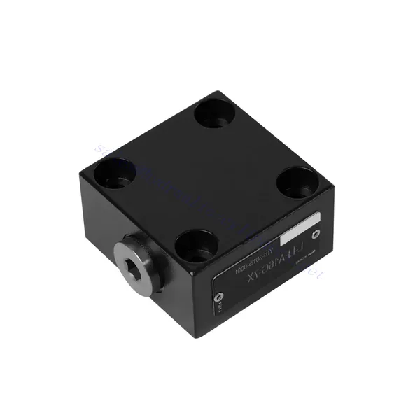
L-LFA Series Directional Control Hydraulic Valve

The L-LFA series directional control hydraulic valve is a cutting-edge component designed to deliver precise control and optimal performance in hydraulic systems. With its advanced features and robust construction, this valve provides reliable and efficient directional control for various applications.
The L-LFA series directional control hydraulic valve is a game-changer for hydraulic systems, offering precise directional control, versatility, and durability. By following the recommended usage methods and maintenance guidelines, you can harness the full potential of the L-LFA series valve and experience enhanced control, efficiency, and productivity in your hydraulic applications. Upgrade your hydraulic system today and unlock the advantages of precision and efficiency with the L-LFA series directional control hydraulic valve.
L-LFA Series Directional Control Hydraulic Valve Key Characteristics:
- Accurate Directional Control:
- The L-LFA series valve offers exceptional directional control, allowing precise and efficient management of fluid flow in hydraulic systems.
- This characteristic enables operators to direct hydraulic fluid to specific actuators or hydraulic components, facilitating smooth and controlled movement.
- Versatile Configuration Options:
- This valve is available in various configurations, including 2-way, 3-way, and 4-way options, ensuring compatibility with diverse hydraulic system requirements.
- The 2-way configuration facilitates simple on/off control, while the 3-way and 4-way configurations enable more complex functions such as cylinder extension, retraction, and bi-directional control.
- High-Performance Construction:
- The L-LFA series valve is engineered with high-quality materials and precision manufacturing techniques to ensure durability and longevity.
- Its robust construction allows it to withstand high pressures, temperature variations, and harsh operating conditions, ensuring reliable performance even in demanding environments.
- Szybki czas reakcji:
- This valve boasts an impressive response time, enabling rapid and efficient fluid flow control within the hydraulic system.
- The quick response time facilitates precise and immediate adjustments, resulting in enhanced system performance and reduced energy consumption.
L-LFA Series Directional Control Hydraulic Valve Parameter:
| Maximum working pressure | Without directional valve | bar | 420 | |||||
| – Oil port A、B、X、Z1、Z2 | bar | 315; 350; 420(Depends on top-mounted directional valve) | ||||||
| – Oil port Y | bar | Equivalent to the return pressure of a top-mounted directional valve | ||||||
| Płyn | Olej mineralny odpowiedni do uszczelnień NBR i FKM | |||||||
| Ester fosforanowy do uszczelnień FKM | ||||||||
| Zakres temperatur cieczy | ℃ | -30 do +80 (uszczelnienie NBR) | ||||||
| -20 do +80 (uszczelnienie FKM) | ||||||||
| Zakres lepkości | mm2/S | 2.8 to 380 | ||||||
| Stopień skażenia | Maximum permissible degree of fluid contamination: Class 9. NAS 1638 or 20/18/15 , ISO4406 | |||||||
L-LFA Series Directional Control Hydraulic Valve Advantages:
• Basic type D with remote control
• With stroke limiter H
• Built-in shuttle valve G
• Built-in directional seat valve R, RF
• Can be equipped with directional valve WE
Usage Method Of L-LFA Series Directional Control Hydraulic Valve:
- Ocena systemu:
- Evaluate your hydraulic system and identify the specific directional control requirements.
- Determine whether the L-LFA series valve suits your system based on flow rates, pressure ratings, and compatibility with your application.
- Wybór zaworu:
- Select the appropriate variant of the L-LFA series valve based on your system parameters and directional control needs.
- Consider factors such as valve type (2-way, 3-way, or 4-way), flow capacity, pressure rating, and compatibility with your specific application.
- Instalacja:
- Follow the manufacturer’s installation instructions carefully to ensure proper alignment and secure valve mounting.
- Use compatible hydraulic fittings, adapters, and seals to establish leak-free connections. Tighten the connections adequately, avoiding overtightening that could damage the valve or fittings.
- Integracja systemów:
- Connect the hydraulic lines to the appropriate ports of the L-LFA series valve, ensuring the correct flow direction.
- Verify that the valve is installed in the correct orientation, as indicated by the directional arrows on the valve body.
- Obsługa i kontrola:
- Familiarize yourself with the control mechanisms of the L-LFA Series Valve, such as levers, knobs, or solenoids.
- Ensure that the valve is actuated correctly and that the desired hydraulic flow is achieved based on the system requirements.
How To Install A Hydraulic Pressure Relief Valve?
Installing a hydraulic pressure relief valve is a crucial step in ensuring the safety and proper functioning of a hydraulic system. Here’s a step-by-step guide on how to install a hydraulic pressure relief valve:
- Zidentyfikuj zawór: Determine the specific type and model of the hydraulic pressure relief valve you work with. Ensure it is suitable for your application and compatible with your hydraulic system requirements.
- Gather the Required Tools and Materials: Collect the necessary tools and materials, including appropriate hydraulic fittings, adapters, wrenches, Teflon tape (thread sealant), and a pressure gauge if needed. Refer to the manufacturer’s instructions for any specific tools or components required.
- Prepare the Hydraulic System: Shut down the hydraulic system and relieve pressure by activating the relief valve or retracting hydraulic cylinders. This step is crucial for safety and prevents accidental movement or hydraulic fluid release.
- Identify the Pressure Relief Point: Determine the optimal location to install the hydraulic pressure relief valve in your hydraulic system. It should be positioned downstream of the pump before any sensitive components to protect them from excessive pressure. Consult the hydraulic system schematic or seek professional advice if necessary.
- Mount the Valve: Securely mount the hydraulic pressure relief valve in the chosen location using appropriate brackets or clamps. Ensure the valve is positioned correctly, aligning the inlet and outlet ports with the flow direction. Follow the manufacturer’s instructions for specific mounting requirements.
- Connect the Inlet and Outlet Ports: Attach hydraulic hoses or tubing to the inlet and outlet ports of the relief valve. Use suitable hydraulic fittings and adapters to create a leak-free connection. Apply Teflon tape or thread sealant to the male threads of the fittings to ensure a secure and sealed connection. Tighten the connections using wrenches to avoid leaks, but be careful not to overtighten.
- Set the Pressure Relief Setting: Most hydraulic pressure relief valves come with an adjustable pressure relief setting. Adjust the relief valve to the desired pressure relief point using the manufacturer’s guidelines. Some valves may require a pressure gauge to accurately set the relief pressure. Install the pressure gauge temporarily, if needed, and adjust the relief valve until the desired pressure is achieved.
- Przetestuj system: Once the hydraulic pressure relief valve is installed, slowly restore hydraulic system pressure. Monitor the pressure gauge or observe the system behavior to ensure that the relief valve functions correctly. The relief valve should open and divert excess pressure when it reaches the set point, preventing damage to the system.
- Monitor and Maintain: Regularly inspect the hydraulic pressure relief valve for any signs of leakage, damage, or reduced performance. Clean the valve and surrounding area to remove dirt and debris that may affect its operation. Follow the manufacturer’s recommended maintenance schedule and guidelines to ensure optimal performance and longevity.
Możliwości i pojemność fabryki:
(1) Montaż
Dysponujemy najwyższej klasy niezależną platformą badawczo-rozwojową. Warsztat produkcji siłowników hydraulicznych posiada cztery półautomatyczne linie montażowe siłowników podnoszących i jedną automatyczną linię montażową siłowników przechyłu, o projektowanej rocznej zdolności produkcyjnej 1 miliona sztuk. Specjalny warsztat cylindrów jest wyposażony w różne specyfikacje półautomatycznego systemu montażu czyszczącego o projektowanej rocznej zdolności produkcyjnej 200 000 i wyposażony w słynny sprzęt do obróbki CNC, centrum obróbcze, specjalny sprzęt do precyzyjnej obróbki cylindrów, robot spawalniczy, automatyczna maszyna czyszcząca, automatyczna maszyna do montażu cylindrów i automatyczna linia produkcyjna do malowania. Istniejący krytyczny sprzęt składa się z ponad 300 zestawów. Optymalna alokacja i efektywne wykorzystanie zasobów sprzętowych zapewniają wymagania dotyczące dokładności produktów i spełniają potrzeby wysokiej jakości produktów.


(2) Obróbka
Warsztat obróbki skrawaniem jest wyposażony w niestandardowe centrum tokarskie z pochyloną szyną, centrum obróbcze, szybkobieżną honownicę, robota spawalniczego i inny powiązany sprzęt, który może obsługiwać przetwarzanie rur cylindrycznych o maksymalnej średnicy wewnętrznej 400 mm i maksymalnej długości 6 metrów.


(3) Spawanie


(4) Malowanie i powlekanie
Z małymi i średnimi automatycznymi liniami do powlekania farbami na bazie wody, w celu osiągnięcia automatycznego załadunku i rozładunku robota oraz automatycznego natryskiwania, wydajność projektowa 4000 sztuk na zmianę;
Posiadamy również półautomatyczną linię do produkcji farb do dużych cylindrów napędzaną łańcuchem napędowym, o wydajności 60 skrzyń na zmianę.


(5) Testowanie
Dysponujemy najwyższej klasy urządzeniami kontrolnymi i stanowiskami testowymi, aby zapewnić, że wydajność cylindra spełnia wymagania.


Jesteśmy jednym z najlepszych producentów cylindrów hydraulicznych. Oferujemy kompleksową ofertę cylindrów hydraulicznych. Dostarczamy również… przekładnie rolnicze. Eksportowaliśmy nasze produkty do klientów na całym świecie i zdobyliśmy dobrą reputację dzięki najwyższej jakości produktów i usług posprzedażnych. Zapraszamy klientów w kraju i za granicą do kontaktu z nami w celu negocjacji biznesowych, wymiany informacji i współpracować z nami!