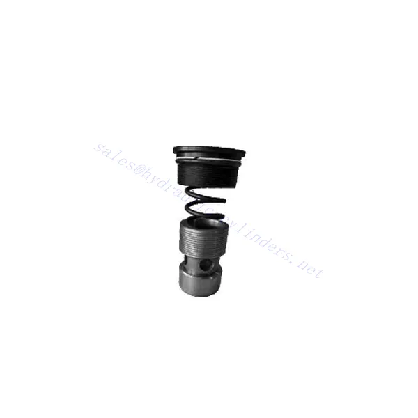
M-SR Series Check Hydraulic Valve Cartridge
Jako jeden z producentów, dostawców i eksporterów produktów mechanicznych, oferujemy cylindry hydrauliczne i wiele innych produktów.
Prosimy o kontakt w celu uzyskania szczegółowych informacji.
Poczta:sales@hydraulic-cylinders.net
Producent dostawca eksporter siłowników hydraulicznych.
M-SR Series Check Hydraulic Valve Cartridge
The M-SR series check hydraulic valve cartridge is versatile and essential in hydraulic systems. This valve cartridge is designed to regulate fluid flow and prevent backflow and offers reliable performance, durability, and ease of installation.
The M-SR series check hydraulic valve cartridge is a reliable and efficient solution for fluid control in hydraulic systems. With efficient check valve functionality, compact design, high flow capacity, and robust construction, this valve cartridge ensures optimal system performance, prevents backflow, and enhances overall efficiency. By following the recommended usage methods and maintenance practices, the M-SR series check hydraulic valve cartridge delivers reliable operation and extends the lifespan of hydraulic systems. Upgrade your hydraulic system with the m-sr series check hydraulic valve cartridge and experience efficient and reliable fluid control.
M-SR Series Check Hydraulic Valve Cartridge Key Characteristics:
- Efektywna funkcjonalność zaworu zwrotnego:
- The M-SR series valve cartridge features a built-in check valve mechanism that enables the unidirectional flow of hydraulic fluid.
- It effectively prevents backflow and ensures fluid flows in the desired direction, minimizing the risk of system damage and inefficiency.
- Kompaktowa i wszechstronna konstrukcja:
- The valve cartridge is compact, making it suitable for applications with limited space or where weight considerations are crucial.
- Its versatile design allows easy integration into various hydraulic systems, including mobile machinery, industrial equipment, and hydraulic power units.
- Wysoka przepustowość:
- Despite its compact size, the M-SR series valve cartridge offers high flow capacity, allowing for efficient fluid transfer and system performance.
- It minimizes pressure drops, ensuring optimal hydraulic power delivery to actuators and other components.
- Solidna konstrukcja:
- Constructed from high-quality materials, the M-SR series valve cartridge demonstrates excellent durability and resistance to wear and corrosion.
- It is designed to withstand demanding operating conditions, prolonging the valve cartridge’s lifespan and reducing maintenance requirements.
M-SR Series Check Hydraulic Valve Cartridge Parameter:
| Specyfikacje | bar | NG6-30 | |||||
| Maksymalne ciśnienie robocze | bar | 315 | |||||
| Ciśnienie pęknięcia | bar | Refer to the characteristic curve | |||||
| Maksymalny przepływ | l/min | Refer to the characteristic curve | |||||
| Zakres lepkości | mm2/S | 2.8 to 380 | |||||
| Zakres temperatur cieczy | ℃ | -30 to +80(NBR seals) | |||||
| -20 do +80 (uszczelki FKM) | |||||||
| Płyn | Olej mineralny odpowiedni do uszczelnień NBR i FKM | ||||||
| Ester fosforanowy do uszczelnień FKM | |||||||
| Stopień skażenia | Maksymalny dopuszczalny stopień zanieczyszczenia płynem: Klasa 9. NAS 1638 lub 20/18/15, ISO4406 | ||||||
| Rozmiar | 8 | 10 | 15 | 20 | 25 | 30 | |
| Weight: Right angled check valve cartridge | kg | 0.03 | 0.05 | 0.08 | 0.14 | 0.32 | 0.47 |
M-SR Series Check Hydraulic Valve Cartridge Advantages:
NG6-30
• Stosowany w montażu bloków kanałów olejowych
• Leak-free closure
• Various opening pressures available (see model description)
Usage Method Of M-SR Series Check Hydraulic Valve Cartridge:
- Analiza systemu:
- Before installation, thoroughly analyze the hydraulic system to determine the specific requirements and operational parameters.
- Consider factors such as flow rates, pressure ratings, and compatibility with the M-SR series valve cartridge.
- Wybór zaworu:
- Select the appropriate M-SR series valve cartridge variant based on the system requirements and specifications.
- Należy wziąć pod uwagę takie czynniki, jak przepustowość, ciśnienie znamionowe i kompatybilność z innymi komponentami systemu.
- Instalacja:
- Follow the manufacturer’s instructions for properly installing the M-SR series valve cartridge in the hydraulic system.
- Ensure a secure fit within the valve cavity, proper alignment with the fluid flow path, and appropriate sealing to prevent leaks.
- Kierunek przepływu cieczy:
- Ensure the M-SR Series Valve Cartridge is installed in the correct orientation, allowing for the desired fluid flow direction.
- Wyrównaj wkład zaworu ze ścieżką przepływu w układzie, zapewniając właściwe zazębienie mechanizmu zaworu zwrotnego.
How Does A Hydraulic Diverter Valve Work?
A hydraulic diverter valve is a key component in hydraulic systems that allows the operator to redirect hydraulic fluid flow from one path to another. It provides flexibility in controlling the flow direction and enables the use of multiple hydraulic actuators with a single hydraulic power source. Here’s a breakdown of how a hydraulic diverter valve works:
- Struktura zaworu:
- A hydraulic diverter valve typically consists of a valve body with multiple ports, a movable spool or ball, and actuators such as levers, solenoids, or pilot pressure mechanisms.
- The valve body contains internal passages and chambers that direct the flow of hydraulic fluid.
- Drogi przepływu cieczy:
- The diverter valve has multiple ports that connect to different hydraulic components in the system, such as the pump, reservoir, actuators, and other valves.
- These ports include an inlet port, outlet ports, and work ports, each serving a specific purpose in controlling the fluid flow.
- Spool or Ball:
- The valve body houses a movable spool or ball that controls the flow of hydraulic fluid.
- The spool can slide within the valve body, while the ball can rotate or move linearly to open or close specific passages.
- Mechanizmy napędowe:
- Hydraulic diverter valves can be actuated manually, electrically, or hydraulically, depending on the specific design and application requirement.
- Manual actuation involves levers or handles that the operator physically moves to position the spool or ball.
- Electrical actuation utilizes solenoids that receive electrical signals to shift the spool or ball, allowing for remote control and automation.
- Hydraulic actuation employs pilot pressure to move the spool or ball, often in conjunction with electrical or manual control.
- Pozycje zaworów:
- Depending on the valve design, there are typically multiple positions that the spool or ball can assume, each corresponding to a specific flow path.
- Common positions include neutral, where all ports are blocked, and various actuating positions that allow flow between specific ports.
- As the spool or ball shifts, it aligns with specific ports, opening or closing passages and directing the hydraulic fluid accordingly.
- Dane wejściowe operatora:
- The operator engages the hydraulic diverter valve by actuating the manual lever, applying electrical signals to solenoids, or manipulating pilot pressure.
- Dane wejściowe określają żądaną pozycję zaworu, która z kolei określa kierunek przepływu i działanie siłowników hydraulicznych.
- Działanie systemu:
- Once the hydraulic diverter valve is in the desired position, hydraulic fluid flows through the appropriate passages and ports.
- This flow of fluid can be directed to different hydraulic actuators, allowing for selective control of the actuator’s movement or operation.
Możliwości i pojemność fabryki:
(1) Montaż
Dysponujemy najwyższej klasy niezależną platformą badawczo-rozwojową. Warsztat produkcji siłowników hydraulicznych posiada cztery półautomatyczne linie montażowe siłowników podnoszących i jedną automatyczną linię montażową siłowników przechyłu, o projektowanej rocznej zdolności produkcyjnej 1 miliona sztuk. Specjalny warsztat cylindrów jest wyposażony w różne specyfikacje półautomatycznego systemu montażu czyszczącego o projektowanej rocznej zdolności produkcyjnej 200 000 i wyposażony w słynny sprzęt do obróbki CNC, centrum obróbcze, specjalny sprzęt do precyzyjnej obróbki cylindrów, robot spawalniczy, automatyczna maszyna czyszcząca, automatyczna maszyna do montażu cylindrów i automatyczna linia produkcyjna do malowania. Istniejący krytyczny sprzęt składa się z ponad 300 zestawów. Optymalna alokacja i efektywne wykorzystanie zasobów sprzętowych zapewniają wymagania dotyczące dokładności produktów i spełniają potrzeby wysokiej jakości produktów.


(2) Obróbka
Warsztat obróbki skrawaniem jest wyposażony w niestandardowe centrum tokarskie z pochyloną szyną, centrum obróbcze, szybkobieżną honownicę, robota spawalniczego i inny powiązany sprzęt, który może obsługiwać przetwarzanie rur cylindrycznych o maksymalnej średnicy wewnętrznej 400 mm i maksymalnej długości 6 metrów.

(3) Spawanie

(4) Malowanie i powlekanie
Z małymi i średnimi automatycznymi liniami do powlekania farbami na bazie wody, w celu osiągnięcia automatycznego załadunku i rozładunku robota oraz automatycznego natryskiwania, wydajność projektowa 4000 sztuk na zmianę;
Posiadamy również półautomatyczną linię do produkcji farb do dużych cylindrów napędzaną łańcuchem napędowym, o wydajności 60 skrzyń na zmianę.


(5) Testowanie
Dysponujemy najwyższej klasy urządzeniami kontrolnymi i stanowiskami testowymi, aby zapewnić, że wydajność cylindra spełnia wymagania.

Jesteśmy jednym z najlepszych producentów cylindrów hydraulicznych. Oferujemy kompleksową ofertę cylindrów hydraulicznych. Dostarczamy również… przekładnie rolnicze. Eksportowaliśmy nasze produkty do klientów na całym świecie i zdobyliśmy dobrą reputację dzięki najwyższej jakości produktów i usług posprzedażnych. Zapraszamy klientów w kraju i za granicą do kontaktu z nami w celu negocjacji biznesowych, wymiany informacji i współpracować z nami!
Siłownik hydrauliczny Zastosowanie:
