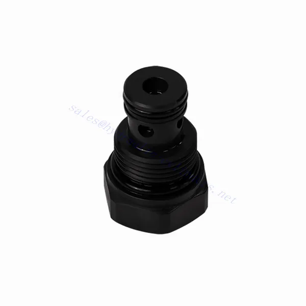
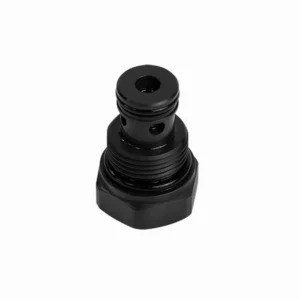
Wkład zaworu zwrotnego hydraulicznego serii RVM
Jako jeden z producentów, dostawców i eksporterów produktów mechanicznych, oferujemy cylindry hydrauliczne i wiele innych produktów.
Prosimy o kontakt w celu uzyskania szczegółowych informacji.
Poczta:sales@hydraulic-cylinders.net
Producent dostawca eksporter siłowników hydraulicznych.
Wkład zaworu zwrotnego hydraulicznego serii RVM
Wkład zaworu zwrotnego serii RVM to niezawodny i wszechstronny element zapewniający optymalną kontrolę przepływu w układach hydraulicznych. Zaprojektowany z myślą o wydajnej i precyzyjnej regulacji przepływu hydraulicznego, wkład zaworu oferuje wyjątkową wydajność, trwałość i łatwość obsługi.
Wkład hydrauliczny z zaworem zwrotnym serii RVM to niezawodne i wydajne rozwiązanie do regulacji przepływu cieczy w układach hydraulicznych. Dzięki wydajnej funkcji zaworu zwrotnego, solidnej konstrukcji, kompaktowej budowie i wysokiej przepustowości, ten wkład zapewnia optymalną wydajność i minimalizuje ryzyko uszkodzenia układu. Dzięki przestrzeganiu zalecanych metod użytkowania i konserwacji, wkład hydrauliczny z zaworem zwrotnym serii RVM zapewnia niezawodną pracę i wydłuża żywotność układów hydraulicznych. Zmodernizuj swój układ hydrauliczny dzięki wkładowi hydraulicznego zaworu zwrotnego serii RVM i ciesz się zwiększoną wydajnością regulacji przepływu cieczy.
Główne cechy wkładu zaworu zwrotnego hydraulicznego serii RVM:
- Efektywna funkcjonalność zaworu zwrotnego:
- Wkład zaworowy serii RVM wyposażony jest w niezwykle wydajny mechanizm zaworu zwrotnego, który umożliwia jednokierunkowy przepływ płynu hydraulicznego.
- Skutecznie zapobiega cofaniu się płynu, zapewniając płynną pracę i minimalizując ryzyko uszkodzenia układu hydraulicznego.
- Solidna konstrukcja:
- Wykonane z materiałów najwyższej jakości wkłady zaworowe serii RVM są wyjątkowo trwałe i odporne na zużycie, co zapewnia długą żywotność.
- Solidna konstrukcja pozwala na pracę w środowiskach o wysokim ciśnieniu i trudnych warunkach eksploatacji.
- Kompaktowa i wszechstronna konstrukcja:
- Wkład zaworowy jest kompaktowy, dzięki czemu nadaje się do zastosowań, w których przestrzeń i waga są ograniczone.
- Uniwersalna konstrukcja pozwala na łatwą integrację z różnymi układami hydraulicznymi, w tym maszynami przemysłowymi, urządzeniami mobilnymi i agregatami napędowymi.
- Wysoka przepustowość:
- Pomimo kompaktowych rozmiarów, wkład zaworowy serii RVM charakteryzuje się dużą przepustowością, co umożliwia efektywny transfer cieczy i optymalną wydajność systemu.
- Minimalizuje spadki ciśnienia, dostarczając maksymalną moc hydrauliczną do siłowników i innych podzespołów.
Parametry wkładu zaworu zwrotnego hydraulicznego serii RVM:
| Waga | kg | 0.12 |
| Maksymalne ciśnienie robocze | bar | 350 |
| Ciśnienie pęknięcia | bar | 0.2 0.5 |
| Maksymalny przepływ | l/min | 30 |
| Zakres lepkości | mm2/S | Zalecenie 30~80, pozwolenie 20~380 |
| Zakres temperatur cieczy | ℃ | -30 do +80 (uszczelnienie NBR) |
| -20 do +80 (uszczelnienie FKM) | ||
| Płyn | Olej mineralny odpowiedni do uszczelnień NBR i FKM | |
| Ester fosforanowy do uszczelnień FKM | ||
| Stopień skażenia | Maksymalny dopuszczalny stopień zanieczyszczenia płynem: Klasa 9. NAS 1638 lub 20/18/15, ISO4406 | |
Zalety zaworów zwrotnych hydraulicznych serii RVM:
• Uszczelnienie bez przecieków
• Struktura wkładu do montażu bloku olejowego
Metoda użytkowania wkładu zaworu zwrotnego hydraulicznego serii RVM :
- Analiza systemu:
- Przed montażem należy dokładnie przeanalizować układ hydrauliczny w celu określenia szczegółowych wymagań i parametrów roboczych.
- Należy wziąć pod uwagę takie czynniki, jak natężenie przepływu, ciśnienie znamionowe i kompatybilność wkładów zaworowych serii RVM.
- Wybór zaworu:
- Wybierz odpowiedni wariant wkładu zaworowego serii RVM na podstawie wymagań i specyfikacji systemu.
- Należy wziąć pod uwagę takie czynniki, jak przepustowość, ciśnienie znamionowe i kompatybilność z innymi komponentami systemu.
- Instalacja:
- Aby prawidłowo zamontować wkład zaworowy serii RVM w układzie hydraulicznym, należy postępować zgodnie z instrukcjami producenta.
- Aby zapobiec wyciekom, należy zapewnić bezpieczne dopasowanie do wnęki zaworu, właściwe wyrównanie ze ścieżką przepływu cieczy oraz odpowiednie uszczelnienie.
- Kierunek przepływu cieczy:
- Sprawdź, czy wkład zaworu serii RVM został zainstalowany w prawidłowym położeniu, umożliwiającym pożądany kierunek przepływu cieczy.
- Wyrównaj wkład zaworu ze ścieżką przepływu w układzie, zapewniając właściwe zazębienie mechanizmu zaworu zwrotnego.
Jak działa zawór sterujący przepływem hydraulicznym?
Zawór sterujący przepływem hydraulicznym to urządzenie służące do regulacji i sterowania prędkością płynu hydraulicznego w układzie hydraulicznym. Umożliwia operatorowi regulację natężenia przepływu płynu, zapobiegając w ten sposób zmniejszeniu prędkości siłowników hydraulicznych lub kontrolując szybkość przesyłu energii. Oto wyjaśnienie działania zaworu sterującego przepływem hydraulicznym:
- Struktura zaworu:
- Zawór sterujący przepływem hydraulicznym zazwyczaj składa się z korpusu zaworu z portami wlotowymi i wylotowymi, ruchomego suwaka lub grzybka i mechanizmu uruchamiającego.
- Korpus zaworu zawiera wewnętrzne kanały i komory, które kontrolują przepływ płynu hydraulicznego.
- Drogi przepływu cieczy:
- Zawór sterujący przepływem ma otwór wlotowy, który łączy się ze źródłem zasilania hydraulicznego, na przykład pompą, oraz otwór wylotowy, który łączy się z siłownikiem hydraulicznym lub innym elementem.
- Zawór zapewnia różne ścieżki przepływu cieczy, umożliwiając jej kontrolowanie i regulację.
- Szpula lub grzybek:
- W korpusie zaworu znajduje się ruchomy suwak lub grzybek, który reguluje przepływ płynu hydraulicznego.
- Szpula może przesuwać się w korpusie zaworu, natomiast grzybek może poruszać się liniowo lub obracać, otwierając lub zamykając określone kanały.
- Mechanizm uruchamiający:
- Zawory sterujące przepływem hydraulicznym mogą być uruchamiane ręcznie, elektrycznie lub innymi sposobami, zależnie od konkretnych wymagań konstrukcyjnych i zastosowania.
- Sterowanie ręczne polega na ustawieniu uchwytu, pokrętła lub dźwigni w celu odpowiedniego ustawienia szpuli lub grzybka.
- Siłownik elektryczny wykorzystuje elektromagnesy, które odbierają sygnały elektryczne w celu przesunięcia szpuli lub grzybka, co umożliwia zdalne sterowanie i automatyzację.
- Pozycje zaworów:
- Zawór sterujący przepływem hydraulicznym zwykle ma wiele pozycji, które może przyjąć suwak lub grzybek, z których każda odpowiada określonej szybkości przepływu.
- Zawór może mieć szereg wstępnie ustawionych pozycji lub umożliwiać ciągłą regulację w celu precyzyjnego dostrojenia natężenia przepływu.
- Gdy szpula lub grzybek się przesuwa, ustawia się on względem określonych kanałów, otwierając je lub zamykając, aby kontrolować przepływ cieczy.
- Regulacja przepływu:
- Regulując położenie suwaka lub grzybka, operator może kontrolować wielkość kanałów przepływowych, regulując w ten sposób natężenie przepływu płynu hydraulicznego.
- Gdy kanały są całkowicie otwarte, płyn przepływa swobodnie, co pozwala na maksymalną szybkość przepływu.
- Częściowe zamknięcie kanałów ogranicza przepływ, zmniejszając jego natężenie i kontrolując prędkość siłowników hydraulicznych.
- Kompensacja ciśnienia:
- Niektóre zawory sterujące przepływem hydraulicznym zawierają mechanizmy kompensacji ciśnienia, które utrzymują stałą szybkość przepływu pomimo zmian ciśnienia w układzie.
- Mechanizmy te zapewniają utrzymanie pożądanej szybkości przepływu nawet wtedy, gdy w układzie występują wahania obciążenia lub ciśnienia.
Możliwości i pojemność fabryki:
(1) Montaż
Dysponujemy najwyższej klasy niezależną platformą badawczo-rozwojową. Warsztat produkcji siłowników hydraulicznych posiada cztery półautomatyczne linie montażowe siłowników podnoszących i jedną automatyczną linię montażową siłowników przechyłu, o projektowanej rocznej zdolności produkcyjnej 1 miliona sztuk. Specjalny warsztat cylindrów jest wyposażony w różne specyfikacje półautomatycznego systemu montażu czyszczącego o projektowanej rocznej zdolności produkcyjnej 200 000 i wyposażony w słynny sprzęt do obróbki CNC, centrum obróbcze, specjalny sprzęt do precyzyjnej obróbki cylindrów, robot spawalniczy, automatyczna maszyna czyszcząca, automatyczna maszyna do montażu cylindrów i automatyczna linia produkcyjna do malowania. Istniejący krytyczny sprzęt składa się z ponad 300 zestawów. Optymalna alokacja i efektywne wykorzystanie zasobów sprzętowych zapewniają wymagania dotyczące dokładności produktów i spełniają potrzeby wysokiej jakości produktów.


(2) Obróbka
Warsztat obróbki skrawaniem jest wyposażony w niestandardowe centrum tokarskie z pochyloną szyną, centrum obróbcze, szybkobieżną honownicę, robota spawalniczego i inny powiązany sprzęt, który może obsługiwać przetwarzanie rur cylindrycznych o maksymalnej średnicy wewnętrznej 400 mm i maksymalnej długości 6 metrów.

(3) Spawanie

(4) Malowanie i powlekanie
Z małymi i średnimi automatycznymi liniami do powlekania farbami na bazie wody, w celu osiągnięcia automatycznego załadunku i rozładunku robota oraz automatycznego natryskiwania, wydajność projektowa 4000 sztuk na zmianę;
Posiadamy również półautomatyczną linię do produkcji farb do dużych cylindrów napędzaną łańcuchem napędowym, o wydajności 60 skrzyń na zmianę.


(5) Testowanie
Dysponujemy najwyższej klasy urządzeniami kontrolnymi i stanowiskami testowymi, aby zapewnić, że wydajność cylindra spełnia wymagania.

Jesteśmy jednym z najlepszych producentów cylindrów hydraulicznych. Oferujemy kompleksową ofertę cylindrów hydraulicznych. Dostarczamy również… przekładnie rolnicze. Eksportowaliśmy nasze produkty do klientów na całym świecie i zdobyliśmy dobrą reputację dzięki najwyższej jakości produktów i usług posprzedażnych. Zapraszamy klientów w kraju i za granicą do kontaktu z nami w celu negocjacji biznesowych, wymiany informacji i współpracować z nami!
Siłownik hydrauliczny Zastosowanie:
