


Zawór hydrauliczny kierunkowy serii WMR z obsługą mechaniczną i ręczną
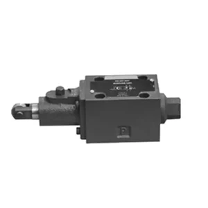

The WMR series directional hydraulic valve with mechanical, manual operation is a cutting-edge solution designed to deliver precise control in hydraulic systems. This valve offers enhanced efficiency and flexibility with its advanced features and robust construction.
The WMR series directional hydraulic valve with mechanical, manual operation is a reliable and versatile solution for hydraulic systems. Its automatic and manual operation and precise directional control offer enhanced flexibility and control for various applications. Following the recommended usage methods and adhering to regular maintenance practices, the WMR series valve will continue providing efficient and reliable operation. Upgrade your hydraulic system with the WMR series directional hydraulic valve and experience the benefits of enhanced control and versatility.
WMR Series Directional Hydraulic Valve With Mechanical, Manual Operation Key Characteristics:
- Mechaniczna, obsługa ręczna:
- The WMR series valve features a mechanical, manual operation, allowing operators to control the valve position manually.
- Zapewnia to elastyczność i kontrolę w zastosowaniach, w których wymagana lub pożądana jest obsługa ręczna.
- Kontrola kierunkowa:
- Ten zawór hydrauliczny umożliwia precyzyjną kontrolę kierunku przepływu cieczy w układzie hydraulicznym.
- Umożliwia operatorom wybór pożądanej ścieżki przepływu, zapewniając wydajną i niezawodną pracę.
- Trwała konstrukcja:
- The WMR series valve is constructed with high-quality materials, ensuring durability and longevity.
- Jego solidna konstrukcja wytrzymuje trudne warunki pracy i gwarantuje niezawodną wydajność.
- Szeroki zakres zastosowań:
- The WMR series valve suits various industries and applications, including manufacturing, construction, agriculture, etc.
- It can be utilized in hydraulic systems that require accurate and efficient fluid control.
WMR Series Directional Hydraulic Valve With Mechanical, Manual Operation Parameter:
NG6
| Pozycja instalacji | Fakultatywny | ||
| Zakres temperatur cieczy | ℃ | -30 do +80 (uszczelki NBR) | |
| -20 do +80 (uszczelki FKM) | |||
| Maksymalne ciśnienie robocze portu | Port ABP | bar | 315 |
| Port T | bar | 60 | |
| Maksymalny przepływ | l/min | 60 | |
| Przekrój przepływu (przełączanie położenia neutralnego) | Typ Q | mm2 | Dla symbolu Q, 6% przekroju nominalnego |
| Typ W | mm2 | Dla symbolu W, 3% przekroju nominalnego | |
| Płyn | Olej mineralny; ester fosforanowy | ||
| Zakres lepkości | mm2/S | 2,8 do 500 | |
| Stopień skażenia | Maksymalny dopuszczalny stopień zanieczyszczenia płynem: Klasa 9. NAS 1638 lub 20/18/15, ISO4406 | ||
| Waga | kg | 1.4 | |
NG10
| Pozycja instalacji | Fakultatywny | ||
| Zakres temperatur cieczy | ℃ | -30 do +80 (uszczelki NBR) | |
| -20 do +80 (uszczelki FKM) | |||
| Maksymalne ciśnienie robocze portu | Port ABP | bar | 315 |
| Port T | bar | 60 | |
| Maksymalny przepływ | l/min | 120 | |
| Przekrój przepływu (przełączanie położenia neutralnego) | Typ V | mm2 | 11(A/B → T);10.3(P → A/B) |
| Typ W | mm2 | 2,5(A/B → T) | |
| Typ Q | mm2 | 5.5(A/B → T) | |
| Płyn | Olej mineralny; ester fosforanowy | ||
| Zakres lepkości | mm2/S | 2,8 do 500 | |
| Stopień skażenia | Maksymalny dopuszczalny stopień zanieczyszczenia płynem: Klasa 9. NAS 1638 lub 20/18/15, ISO4406 | ||
| Waga | kg | 4 | |
WMR Series Directional Hydraulic Valve With Mechanical, Manual Operation Advantages:
• Zawór suwakowy kierunkowy bezpośredniego działania Zawór suwakowy kierunkowy bezpośredniego działania
• Scroll wheel can rotate 90°
• Nineteen standard slide valve functions
Usage Method Of WMR Series Directional Hydraulic Valve With Mechanical, Manual Operation:
- Integracja systemów:
- Identify the appropriate location for the WMR series valve within the hydraulic system, considering the desired flow direction and control requirements.
- Ensure compatibility with the system’s pressure and flow specifications.
- Zamontuj zawór w sposób bezpieczny, używając odpowiednich wsporników lub akcesoriów montażowych.
- Połączenia płynne:
- Wybierz kompatybilne złączki hydrauliczne i węże, aby zapewnić bezpieczne i szczelne połączenia.
- Follow the manufacturer’s instructions for proper torque values during the installation process.
- Aby zapewnić niezawodne uszczelnienie, należy stosować odpowiednie uszczelniacze gwintów lub taśmę.
- Obsługa ręczna:
- Familiarize yourself with the manual operation mechanism of the valve, including the lever or knob used to control the valve position.
- Upewnij się, że operator rozumie prawidłową procedurę ręcznej regulacji położenia zaworu.
- Kalibracja systemu:
- Calibrate the valve position and movement according to the desired flow direction and control requirements.
- Wyreguluj zawór ręcznie, aby uzyskać pożądany przepływ i zapewnić jego prawidłowe działanie.
How To Adjust Hydraulic Valve Lifters?
Adjusting hydraulic valve lifters is a crucial maintenance task to ensure proper engine performance and prevent issues like valve train noise and reduced power. Here’s a step-by-step guide on how to adjust hydraulic valve lifters:
- Przygotuj silnik:
- Before starting the adjustment process, make sure the engine is turned off and cool to the touch.
- Remove any components necessary to access the valve covers, such as the air cleaner assembly or spark plug wires.
- Określ prawidłową kolejność regulacji zaworów:
- Consult the engine manufacturer’s specifications or service manual to determine the correct valve adjustment sequence for your specific engine.
- Some engines have a firing order that dictates the sequence, while others have specific instructions based on cylinder numbering.
- Znajdź położenie górnego martwego punktu (GMP):
- Rotate the engine’s crankshaft in the normal direction of rotation until the number one piston reaches the top dead center (TDC) position on its compression stroke.
- Use a timing mark on the harmonic balancer or flywheel and a timing pointer to determine the TDC position accurately.
- Adjusting Valve Lifters:
- Start with the first cylinder in the valve adjustment sequence.
- Remove the valve cover to access the rocker arms and valve lifters.
- Loosen the lock nut on the rocker’s arm using an appropriate wrench or socket.
- Turn the adjusting screw or stud on the rocker’s arm clockwise to decrease the valve clearance or counterclockwise to increase it.
- Check the engine manufacturer’s specifications for the recommended valve clearance. Use a feeler gauge to measure the clearance between the rocker arm and the valve stem.
- Adjust the valve lifter until the proper clearance is achieved. You should feel slight resistance but still be able to move the feeler gauge back and forth.
- Hold the adjusting screw or stud in place and tighten the lock nut securely.
- Powtórz proces:
- Move to the next cylinder in the valve adjustment sequence and repeat steps 4 and 5 until all the valve lifters have been adjusted.
- Ponowny montaż pokryw zaworów:
- Once you’ve completed the valve adjustment on all cylinders, reinstall the valve covers and ensure they are properly sealed to prevent oil leaks.
- Sprawdź jeszcze raz:
- After adjusting the valve lifters, it’s advisable to go through the entire valve adjustment sequence once more to confirm that all clearances are within the specified range.
Możliwości i pojemność fabryki:
(1) Montaż
Dysponujemy najwyższej klasy niezależną platformą badawczo-rozwojową. Warsztat produkcji siłowników hydraulicznych posiada cztery półautomatyczne linie montażowe siłowników podnoszących i jedną automatyczną linię montażową siłowników przechyłu, o projektowanej rocznej zdolności produkcyjnej 1 miliona sztuk. Specjalny warsztat cylindrów jest wyposażony w różne specyfikacje półautomatycznego systemu montażu czyszczącego o projektowanej rocznej zdolności produkcyjnej 200 000 i wyposażony w słynny sprzęt do obróbki CNC, centrum obróbcze, specjalny sprzęt do precyzyjnej obróbki cylindrów, robot spawalniczy, automatyczna maszyna czyszcząca, automatyczna maszyna do montażu cylindrów i automatyczna linia produkcyjna do malowania. Istniejący krytyczny sprzęt składa się z ponad 300 zestawów. Optymalna alokacja i efektywne wykorzystanie zasobów sprzętowych zapewniają wymagania dotyczące dokładności produktów i spełniają potrzeby wysokiej jakości produktów.


(2) Obróbka
Warsztat obróbki skrawaniem jest wyposażony w niestandardowe centrum tokarskie z pochyloną szyną, centrum obróbcze, szybkobieżną honownicę, robota spawalniczego i inny powiązany sprzęt, który może obsługiwać przetwarzanie rur cylindrycznych o maksymalnej średnicy wewnętrznej 400 mm i maksymalnej długości 6 metrów.


(3) Spawanie


(4) Malowanie i powlekanie
Z małymi i średnimi automatycznymi liniami do powlekania farbami na bazie wody, w celu osiągnięcia automatycznego załadunku i rozładunku robota oraz automatycznego natryskiwania, wydajność projektowa 4000 sztuk na zmianę;
Posiadamy również półautomatyczną linię do produkcji farb do dużych cylindrów napędzaną łańcuchem napędowym, o wydajności 60 skrzyń na zmianę.


(5) Testowanie
Dysponujemy najwyższej klasy urządzeniami kontrolnymi i stanowiskami testowymi, aby zapewnić, że wydajność cylindra spełnia wymagania.


Jesteśmy jednym z najlepszych producentów cylindrów hydraulicznych. Oferujemy kompleksową ofertę cylindrów hydraulicznych. Dostarczamy również… przekładnie rolnicze. Eksportowaliśmy nasze produkty do klientów na całym świecie i zdobyliśmy dobrą reputację dzięki najwyższej jakości produktów i usług posprzedażnych. Zapraszamy klientów w kraju i za granicą do kontaktu z nami w celu negocjacji biznesowych, wymiany informacji i współpracować z nami!