
Zawór hydrauliczny sterujący przepływem serii Z2FRM
Jako jeden z producentów, dostawców i eksporterów produktów mechanicznych, oferujemy cylindry hydrauliczne i wiele innych produktów.
Prosimy o kontakt w celu uzyskania szczegółowych informacji.
Poczta:sales@hydraulic-cylinders.net
Producent dostawca eksporter siłowników hydraulicznych.
Zawór hydrauliczny sterujący przepływem serii Z2FRM
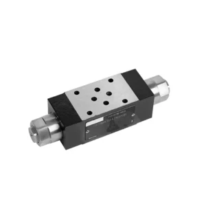
Zawór hydrauliczny z regulacją przepływu serii Z2FRM to najnowocześniejszy element hydrauliczny zaprojektowany z myślą o zrewolucjonizowaniu sterowania i wydajności układów hydraulicznych. Dzięki zaawansowanym funkcjom i wyjątkowej wydajności, zawór ten zapewnia precyzyjną kontrolę przepływu i zwiększa ogólną wydajność maszyn hydraulicznych.
Zawór hydrauliczny z regulacją przepływu serii Z2FRM to przełomowe rozwiązanie zapewniające precyzyjną kontrolę przepływu w układach hydraulicznych. Dzięki niezrównanej precyzji, wszechstronności i trwałości, zawór ten umożliwia operatorom optymalizację wydajności i efektywności maszyn hydraulicznych. Przestrzegając zalecanych metod użytkowania i instrukcji konserwacji, można w pełni wykorzystać potencjał zaworu hydraulicznego z regulacją przepływu serii Z2FRM, zapewniając płynną pracę i niezawodną kontrolę przepływu w układach hydraulicznych. Zmodernizuj swój układ hydrauliczny już dziś i poznaj moc precyzyjnego sterowania hydraulicznego dzięki zaworowi serii Z2FRM.
Główne cechy zaworu hydraulicznego do regulacji przepływu serii Z2FRM:
- Precyzyjna kontrola przepływu:
- Zawór serii Z2FRM oferuje niezrównaną precyzję sterowania natężeniem przepływu płynów hydraulicznych, umożliwiając precyzyjną regulację i optymalizację wydajności.
- Dzięki wysokiej dokładności zawór ten gwarantuje stałą kontrolę przepływu, co przekłada się na zwiększoną wydajność i wzrost produktywności systemu.
- Wszechstronne zastosowania:
- Zawór serii Z2FRM to niezwykle wszechstronny zawór, kompatybilny z szeroką gamą układów hydraulicznych, w tym maszynami przemysłowymi, sprzętem budowlanym i zastosowaniami mobilnymi.
- Jego wszechstronność sprawia, że jest idealnym wyborem do różnych układów hydraulicznych, zapewniając niezawodną i wydajną kontrolę przepływu.
- Stabilność ciśnienia i temperatury:
- Zawory serii Z2FRM zaprojektowano tak, aby wytrzymywały zmienne warunki ciśnienia i temperatury, dzięki czemu zapewniają stabilną kontrolę przepływu nawet w wymagających warunkach pracy.
- Gwarantuje stałą wydajność, minimalizuje wahania przepływu i zabezpiecza integralność układu hydraulicznego.
- Solidna konstrukcja:
- Zawór serii Z2FRM charakteryzuje się solidną konstrukcją i jest wykonany z wysokiej jakości materiałów, co gwarantuje trwałość i długotrwałą niezawodność.
- Jego solidna konstrukcja pozwala mu wytrzymać wysokie ciśnienia, wibracje i ekstremalne temperatury, dzięki czemu jest niezawodnym rozwiązaniem w krytycznych zastosowaniach hydraulicznych.
Parametry zaworu hydraulicznego regulującego przepływ serii Z2FRM:
NG6
| Zawór sterujący przepływem | |||||||||||
| Maksymalne ciśnienie robocze – port A | bar | 315 | |||||||||
| Różnica ciśnień ΔP dla swobodnego przepływu powrotnego B do A | Zobacz krzywe charakterystyczne | ||||||||||
| Minimalna różnica ciśnień | bar | od 6 do 14 | |||||||||
| Stabilność ciśnienia do P= 315 bar | % | ±2(Qmax) | |||||||||
| Przepływ | Qmax | l/min | 0.2 | 0.6 | 1.5 | 3 | 6 | 10 | 16 | 25 | 32 |
| Qmin do 100bar | ml/min | 15 | 15 | 15 | 15 | 25 | 50 | 70 | 100 | 250 | |
| Qmin do 315bar | 25 | 25 | 25 | 25 | 25 | 50 | 70 | 100 | 250 | ||
| Płyn | Olej mineralny, ester fosforanowy | ||||||||||
| Zakres temperatur cieczy | ℃ | – 20 do + 80 | |||||||||
| Zakres lepkości | mm2/s | od 10 do 800 | |||||||||
| Stopień skażenia | Maksymalny dopuszczalny stopień zanieczyszczenia płynem: Klasa 9. NAS 1638 lub 20/18/15, ISO4406 | ||||||||||
| Pozycja instalacji | Fakultatywny | ||||||||||
| Zakres temperatur okoliczności | ℃ | -20 do +50 | |||||||||
| Waga | 2FRM6A…2FRM6B… | kg | około 1,3 | ||||||||
| 2FRM6SB… | kg | około 1,5 | |||||||||
| Prostownik | |||||||||||
| Przepływ nominalny | bar | 320 | |||||||||
| Maksymalne ciśnienie robocze | bar | do 210 | |||||||||
| Ciśnienie pęknięcia | bar | 0.7 | |||||||||
| Waga | kg | około 0,9 | |||||||||
NG5/10/16
| Zawór sterujący przepływem | ||||||||||||||||
| Maksymalne ciśnienie robocze – port A | bar | 315 | ||||||||||||||
| Różnica ciśnień ΔP dla swobodnego przepływu powrotnego B do A | Zobacz krzywe charakterystyczne | |||||||||||||||
| Minimalna różnica ciśnień | bar | od 6 do 14 | ||||||||||||||
| Płyn | Olej mineralny, ester fosforanowy | |||||||||||||||
| Zakres temperatur cieczy | ℃ | – 20 do + 80 | ||||||||||||||
| Zakres lepkości | mm2/s | od 10 do 800 | ||||||||||||||
| Stopień skażenia | Maksymalny dopuszczalny stopień zanieczyszczenia płynem: Klasa 9. NAS 1638 lub 20/18/15, ISO4406 | |||||||||||||||
| Rozmiar | mm | 5 | 10 | 16 | ||||||||||||
| Maksymalny przepływ | l/min | 0.2 | 0.6 | 1.2 | 3 | 6 | 10 | 15 | 10 | 16 | 25 | 50 | 60 | 100 | 160 | |
| Przepływ powrotny oleju B do A | ml/min | 0.5 | 0.5 | 0.6 | 0.9 | 1.8 | 3.6 | 6.7 | 2 | 2.5 | 3.5 | 6 | 2.8 | 4.3 | 7.3 | |
| zakres stabilności przepływu (%Qmax)(-20-±80℃) | ±5 | ±3 | ±2 | ±2 | ||||||||||||
| ±2 (P=210 barów) | ±2 (P=350 barów) | |||||||||||||||
| Ciśnienie robocze | bar | 210 | 350 | |||||||||||||
| Min. obniżenie ciśnienia | bar | 3-5 | 6-8 | 3-7 | 5-12 | |||||||||||
| Waga | kg | 1.6 | 3.4 | 7.4 | ||||||||||||
| Prostownik | ||||||||||||||||
| Płyn | Olej mineralny, ester fosforanowy | |||||||||||||||
| Zakres temperatur cieczy | -20 do +80 | |||||||||||||||
| Zakres lepkości | od 10 do 800 | |||||||||||||||
| Stopień skażenia | Maksymalny dopuszczalny stopień zanieczyszczenia płynem: Klasa 9. NAS 1638 lub 20/18/15, ISO4406 | |||||||||||||||
| Rozmiar | 5 | 10 | 16 | |||||||||||||
| Przepływ | 15 | 50 | 160 | |||||||||||||
| Ciśnienie robocze | 210 | 315 | 315 | |||||||||||||
| Ciśnienie pęknięcia | 1 | 1.5 | 1.5 | |||||||||||||
| Waga | 0.6 | 3.2 | 9.3 | |||||||||||||
Zalety zaworów hydraulicznych do regulacji przepływu serii Z2FRM:
• Montaż na płycie bazowej – patrz katalog produktów
• Ogranicznik przemieszczenia kompensujący ciśnienie, opcjonalnie
• Opcjonalny zawór jednokierunkowy
• Pokrętło ze skalą, opcjonalna blokada
Metoda użytkowania zaworu hydraulicznego sterującego przepływem serii Z2FRM:
- Ocena systemu:
- Zacznij od oceny konkretnych wymagań swojego układu hydraulicznego, w tym pożądanego natężenia przepływu, zakresów ciśnień i parametrów sterowania przepływem.
- Sprawdź, czy zawór serii Z2FRM sprawdzi się w Twoim zastosowaniu, biorąc pod uwagę jego możliwości sterowania przepływem i kompatybilność z Twoim systemem.
- Wybór zaworu:
- Wybierz odpowiedni wariant zaworu serii Z2FRM na podstawie parametrów swojego systemu, oczekiwanego natężenia przepływu i kompatybilności z innymi komponentami systemu.
- Należy wziąć pod uwagę takie czynniki, jak maksymalna przepustowość, ciśnienie znamionowe i warunki pracy.
- Instalacja:
- Należy ściśle przestrzegać instrukcji producenta dotyczących instalacji, aby zapewnić precyzyjne wyrównanie i bezpieczne podłączenie zaworów.
- Należy zwrócić szczególną uwagę na wskaźniki kierunku przepływu, aby upewnić się, że zawór jest prawidłowo umieszczony w układzie hydraulicznym.
- Regulacja kontroli przepływu:
- Po zainstalowaniu zaworu należy dostosować ustawienia przepływu tak, aby uzyskać żądaną szybkość przepływu i spełnić wymagania systemu.
- Precyzyjne dostrojenie zaworu w celu optymalizacji prędkości i wydajności siłowników hydraulicznych, maksymalizując w ten sposób ogólną wydajność systemu.
Jak zamontować zawór hydrauliczny w ciągniku?
Dodanie zaworu hydraulicznego do ciągnika może rozszerzyć jego funkcjonalność i umożliwić korzystanie z osprzętu hydraulicznego i narzędzi. Oto ogólne kroki, które należy wykonać podczas dodawania zaworu hydraulicznego do ciągnika:
- Określ układ hydrauliczny ciągnika:
- Sprawdź, czy Twój ciągnik posiada już układ hydrauliczny. Wiele nowoczesnych ciągników jest wyposażonych w układy hydrauliczne, podczas gdy starsze modele mogą wymagać modyfikacji lub dodatkowych podzespołów.
- Wybierz odpowiedni zawór hydrauliczny:
- Wybierz zawór hydrauliczny, który odpowiada Twoim potrzebom i wymaganiom. Weź pod uwagę takie czynniki, jak natężenie przepływu, ciśnienie znamionowe, liczbę suwaków i kompatybilność z układem hydraulicznym ciągnika.
- Zbierz niezbędne narzędzia i materiały:
- Upewnij się, że masz wszystkie niezbędne narzędzia i materiały do procesu instalacji. Mogą to być klucze, węże hydrauliczne, złączki, wsporniki montażowe i sam zawór hydrauliczny.
- Określ miejsce instalacji:
- Określ idealne miejsce montażu zaworu hydraulicznego w ciągniku. Zazwyczaj znajduje się ono w pobliżu istniejących portów hydraulicznych lub w dogodnym i łatwo dostępnym miejscu.
- Przygotuj ciągnik:
- Przed przystąpieniem do montażu należy wyłączyć silnik ciągnika i zredukować ciśnienie w układzie hydraulicznym, przesuwając dźwignie sterujące hydrauliką do przodu i do tyłu.
- Montaż zaworu hydraulicznego:
- Zamontuj zawór hydrauliczny bezpiecznie, używając odpowiednich wsporników lub elementów montażowych. Upewnij się, że jest on prawidłowo ustawiony i wyrównany z portami hydraulicznymi.
- Podłącz przewody hydrauliczne:
- Podłącz przewody hydrauliczne do portów zaworu, zapewniając bezpieczne połączenie. Użyj odpowiednich złączek i dokręć je dokładnie, aby zapobiec wyciekom.
- Podłącz do układu hydraulicznego ciągnika:
- Zidentyfikuj istniejące porty hydrauliczne lub złącza ciągnika. Podłącz przewody hydrauliczne od zaworu do tych portów, dopasowując odpowiednie końcówki.
- Test szczelności:
- Po wykonaniu wszystkich połączeń, uruchom silnik ciągnika i użyj elementów sterujących hydrauliką. Dokładnie sprawdź wszystkie połączenia pod kątem wycieków płynu hydraulicznego. Niezwłocznie usuń wszelkie wycieki, dokręcając złącza lub wymieniając uszkodzone podzespoły.
- Przetestuj zawór hydrauliczny:
- Włącz sterowanie hydrauliczne i sprawdź działanie nowo zamontowanego zaworu hydraulicznego. Upewnij się, że działa on płynnie i steruje osprzętem hydraulicznym zgodnie z przeznaczeniem.
- Zabezpiecz i chroń węże:
- Zabezpiecz przewody hydrauliczne zaciskami lub wspornikami, aby zapobiec ich kolizji z innymi podzespołami ciągnika lub uszkodzeniu podczas pracy. Rozważ zastosowanie osłon ochronnych na przewody, aby zabezpieczyć je przed czynnikami zewnętrznymi i potencjalnym ścieraniem.
Możliwości i pojemność fabryki:
(1) Montaż
Dysponujemy najwyższej klasy niezależną platformą badawczo-rozwojową. Warsztat produkcji siłowników hydraulicznych posiada cztery półautomatyczne linie montażowe siłowników podnoszących i jedną automatyczną linię montażową siłowników przechyłu, o projektowanej rocznej zdolności produkcyjnej 1 miliona sztuk. Specjalny warsztat cylindrów jest wyposażony w różne specyfikacje półautomatycznego systemu montażu czyszczącego o projektowanej rocznej zdolności produkcyjnej 200 000 i wyposażony w słynny sprzęt do obróbki CNC, centrum obróbcze, specjalny sprzęt do precyzyjnej obróbki cylindrów, robot spawalniczy, automatyczna maszyna czyszcząca, automatyczna maszyna do montażu cylindrów i automatyczna linia produkcyjna do malowania. Istniejący krytyczny sprzęt składa się z ponad 300 zestawów. Optymalna alokacja i efektywne wykorzystanie zasobów sprzętowych zapewniają wymagania dotyczące dokładności produktów i spełniają potrzeby wysokiej jakości produktów.


(2) Obróbka
Warsztat obróbki skrawaniem jest wyposażony w niestandardowe centrum tokarskie z pochyloną szyną, centrum obróbcze, szybkobieżną honownicę, robota spawalniczego i inny powiązany sprzęt, który może obsługiwać przetwarzanie rur cylindrycznych o maksymalnej średnicy wewnętrznej 400 mm i maksymalnej długości 6 metrów.

(3) Spawanie

(4) Malowanie i powlekanie
Z małymi i średnimi automatycznymi liniami do powlekania farbami na bazie wody, w celu osiągnięcia automatycznego załadunku i rozładunku robota oraz automatycznego natryskiwania, wydajność projektowa 4000 sztuk na zmianę;
Posiadamy również półautomatyczną linię do produkcji farb do dużych cylindrów napędzaną łańcuchem napędowym, o wydajności 60 skrzyń na zmianę.


(5) Testowanie
Dysponujemy najwyższej klasy urządzeniami kontrolnymi i stanowiskami testowymi, aby zapewnić, że wydajność cylindra spełnia wymagania.

Jesteśmy jednym z najlepszych producentów cylindrów hydraulicznych. Oferujemy kompleksową ofertę cylindrów hydraulicznych. Dostarczamy również… przekładnie rolnicze. Eksportowaliśmy nasze produkty do klientów na całym świecie i zdobyliśmy dobrą reputację dzięki najwyższej jakości produktów i usług posprzedażnych. Zapraszamy klientów w kraju i za granicą do kontaktu z nami w celu negocjacji biznesowych, wymiany informacji i współpracować z nami!
Siłownik hydrauliczny Zastosowanie:
