

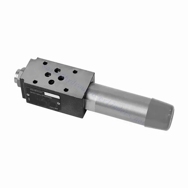
Zawór hydrauliczny redukujący ciśnienie sterowany bezpośrednio serii ZDR
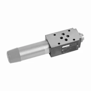

Zawór hydrauliczny redukujący ciśnienie z serii ZDR o bezpośrednim sterowaniu to wysoce wydajny i niezawodny element zapewniający precyzyjną regulację ciśnienia w układach hydraulicznych. Dzięki konstrukcji sterowanej bezpośrednio i wyjątkowej wydajności, zawór ten zapewnia precyzyjną redukcję ciśnienia, dostosowując się do specyficznych wymagań systemu.
Zawór hydrauliczny redukujący ciśnienie z serii ZDR o działaniu bezpośrednim to wydajne rozwiązanie do precyzyjnej regulacji ciśnienia w układach hydraulicznych. Dzięki konstrukcji o działaniu bezpośrednim, precyzyjnej regulacji ciśnienia, szerokiemu zakresowi ciśnienia i wysokiej przepustowości, zawór ten zapewnia wydajną i niezawodną redukcję ciśnienia, chroniąc jednocześnie podzespoły układu. Dzięki przestrzeganiu zalecanych metod użytkowania i konserwacji, zawór serii ZDR zapewnia niezawodną pracę, wydłużając żywotność układów hydraulicznych. Zmodernizuj swój układ hydrauliczny za pomocą zaworu hydraulicznego redukującego ciśnienie z serii ZDR o działaniu bezpośrednim i ciesz się optymalną kontrolą ciśnienia, zwiększając wydajność i produktywność systemu.
Główne cechy zaworów hydraulicznych redukujących ciśnienie bezpośrednio sterowanych serii ZDR:
- Konstrukcja sterowana bezpośrednio:
- Zawór serii ZDR charakteryzuje się konstrukcją sterowaną bezpośrednio, dzięki czemu zapewnia precyzyjną kontrolę ciśnienia bez konieczności stosowania zewnętrznych obwodów pilotowych.
- Taka konstrukcja ułatwia instalację i zmniejsza złożoność układów hydraulicznych.
- Dokładna kontrola ciśnienia:
- Zawór ten zapewnia wyjątkową dokładność regulacji ciśnienia, umożliwiając układom hydraulicznym utrzymanie żądanego zakresu ciśnienia przy zachowaniu wysokiej niezawodności.
- Zapewnia stabilną pracę i chroni wrażliwe elementy systemu przed nadmiernym ciśnieniem.
- Szeroki zakres ciśnień:
- Zawór serii ZDR jest dostępny w różnych zakresach ciśnień, dzięki czemu nadaje się do rozmaitych zastosowań hydraulicznych.
- Elastyczność zakresu ciśnień pozwala na dostosowanie ustawień do konkretnych wymagań systemu i optymalizację wydajności.
- Wysoka przepustowość:
- Zawór ten charakteryzuje się doskonałą przepustowością, co pozwala mu na obsługę dużych przepływów przy jednoczesnym zachowaniu precyzyjnej kontroli ciśnienia.
- Zapewnia skuteczną regulację przepływu cieczy i nieprzerwaną pracę systemu nawet w wymagających zastosowaniach.
Parametry zaworu hydraulicznego redukującego ciśnienie bezpośrednio sterowanego serii ZDR:
| Specyfikacje | NG10 | NG16 | ||
| Płyn | Olej mineralny odpowiedni do uszczelnień NBR i FKM | |||
| Ester fosforanowy do uszczelnień FKM | ||||
| Zakres temperatur cieczy | ℃ | -30 do +80 (uszczelki NBR) | ||
| -20 do +80 (uszczelki FKM) | ||||
| Zakres lepkości | mm2/S | od 10 do 800 | ||
| Stopień skażenia | Maksymalny dopuszczalny stopień zanieczyszczenia płynem: Klasa 9. NAS 1638 lub 20/18/15, ISO4406 | |||
| Ciśnienie nominalne | bar | 315 | ||
| Maksymalne ciśnienie robocze | Port P | bar | 315 | |
| Maksymalne ciśnienie robocze | Port A | bar | 315 | 250 |
| Maksymalne ciśnienie robocze | Port Y | bar | Oddzielne i bezciśnieniowe do zbiornika | |
| Ustawienie ciśnienia | Min. | bar | Zależne od przepływu (patrz krzywe) | |
| Maks. | bar | 50; 100; 200; 315 | 50; 100; 200; 250 | |
| Maksymalny przepływ | l/min | 120 | 220 | |
| Waga | kg | około 6,5 | około 8,8 | |
Zalety zaworów hydraulicznych redukujących ciśnienie bezpośrednio sterowanych serii ZDR:
• Struktura typu kanapkowego
• Montaż powierzchni czołowej odbywa się zgodnie z normami DIN 24340 A i ISO 4401
• Cztery zakresy ciśnienia
• Dwa rodzaje regulacji: pokrętło, śruba regulacyjna z nasadką ochronną
• Z interfejsem manometru
• Opcjonalny zawór kierunkowy
Metoda użytkowania zaworu hydraulicznego redukującego ciśnienie bezpośrednio sterowanego serii ZDR:
- Analiza systemu:
- Przeprowadź szczegółową analizę układu hydraulicznego w celu określenia konkretnych wymagań dotyczących kontroli ciśnienia.
- Należy wziąć pod uwagę maksymalne ciśnienie robocze, pożądany zakres ciśnień i natężenie przepływu.
- Wybór zaworu:
- Select the appropriate ZDR series valve variant based on the system’s pressure control specifications.
- Należy wziąć pod uwagę ciśnienie znamionowe, przepustowość i kompatybilność z innymi komponentami systemu.
- Instalacja:
- Follow the manufacturer’s instructions to correctly install the ZDR series direct-operated pressure-reducing valve in the hydraulic system.
- Zapewnij właściwe ustawienie i solidne połączenia, aby zapobiec wyciekom i zoptymalizować wydajność.
- Kalibrowanie:
- Skalibruj zawór, aby ustawić żądane ciśnienie wylotowe.
- Do dokładnej regulacji ciśnienia i optymalnej kontroli zaworu należy używać manometrów lub innych urządzeń pomiarowych.
Jak działa hydrauliczny zawór selektorowy?
A hydraulic selector valve, also known as a hydraulic diverter valve or hydraulic control valve, is a device used to direct the flow of hydraulic fluid in a hydraulic system. It allows the operator to control the path of fluid flow by selecting different hydraulic circuits or components to operate. Here’s a breakdown of how a hydraulic selector valve works:
- Budowa zaworu:
- Zawór selektorowy hydrauliczny składa się z korpusu z wieloma portami i kanałami wewnętrznymi.
- Zazwyczaj posiada mechanizm uruchamiający, taki jak dźwignia lub elektromagnes, który steruje ruchem szpuli zaworu lub grzybka.
- Konfiguracja portu:
- Zawór selektorowy ma wiele portów, zwykle oznaczonych jako A, B i C, a czasami określanych jako P, T i A/B/C.
- Port P (ciśnienie) łączy się z pompą hydrauliczną lub stroną wysokiego ciśnienia układu.
- Port T (zbiornik) łączy się ze zbiornikiem hydraulicznym lub stroną niskiego ciśnienia układu.
- Porty A, B i C to porty wyjściowe, które łączą się z różnymi obwodami hydraulicznymi lub komponentami.
- Pozycje zaworów:
- Zawór selektorowy może mieć różne położenia, które określają ścieżkę przepływu płynu hydraulicznego.
- Common positions include “A,” “B,” “C,” “AB,” “AC,” and “BC,” depending on the specific valve design.
- Kontrola przepływu cieczy:
- When the valve is in the neutral or default position, typically labeled “N,” the fluid flow is blocked, and no flow occurs between any of the ports.
- Gdy operator uruchamia zawór, przesuwając dźwignię lub włączając elektromagnes, szpula zaworu lub grzybek przesuwa się do innej pozycji, umożliwiając przepływ cieczy.
- Wybór ścieżki przepływu:
- Przesuwając mechanizm uruchamiający, operator może wybrać żądaną ścieżkę przepływu.
- For example, when the valve is in position “A,” fluid flows from port P to port A, allowing the hydraulic circuit or component connected to port A to operate.
- Wiele ścieżek przepływu:
- W zależności od konkretnej konstrukcji zaworu, hydrauliczny zawór selektorowy może zapewniać wiele ścieżek przepływu.
- For instance, in position “AB,” fluid can flow from port P to both ports A and B simultaneously, allowing operation of two separate hydraulic circuits or components.
- Sterowanie i obsługa:
- Mechanizm uruchamiający zawór selektorowy może być ręczny, w którym operator fizycznie porusza dźwignią lub pokrętłem, albo elektryczny lub pneumatyczny, wykorzystujący elektromagnesy i inne urządzenia sterujące.
- Zawory selektorowe sterowane elektrycznie mogą być integrowane z systemami automatycznymi lub sterowane zdalnie.
- Elastyczność systemu:
- Zawory selektorowe hydrauliczne zapewniają elastyczność w projektowaniu i obsłudze systemu.
- Umożliwiają operatorowi przełączanie się między różnymi obwodami hydraulicznymi lub podzespołami, ułatwiając wykonywanie takich zadań, jak pozycjonowanie sprzętu, sterowanie osprzętem czy przełączanie między różnymi narzędziami.
Możliwości i pojemność fabryki:
(1) Montaż
Dysponujemy najwyższej klasy niezależną platformą badawczo-rozwojową. Warsztat produkcji siłowników hydraulicznych posiada cztery półautomatyczne linie montażowe siłowników podnoszących i jedną automatyczną linię montażową siłowników przechyłu, o projektowanej rocznej zdolności produkcyjnej 1 miliona sztuk. Specjalny warsztat cylindrów jest wyposażony w różne specyfikacje półautomatycznego systemu montażu czyszczącego o projektowanej rocznej zdolności produkcyjnej 200 000 i wyposażony w słynny sprzęt do obróbki CNC, centrum obróbcze, specjalny sprzęt do precyzyjnej obróbki cylindrów, robot spawalniczy, automatyczna maszyna czyszcząca, automatyczna maszyna do montażu cylindrów i automatyczna linia produkcyjna do malowania. Istniejący krytyczny sprzęt składa się z ponad 300 zestawów. Optymalna alokacja i efektywne wykorzystanie zasobów sprzętowych zapewniają wymagania dotyczące dokładności produktów i spełniają potrzeby wysokiej jakości produktów.


(2) Obróbka
Warsztat obróbki skrawaniem jest wyposażony w niestandardowe centrum tokarskie z pochyloną szyną, centrum obróbcze, szybkobieżną honownicę, robota spawalniczego i inny powiązany sprzęt, który może obsługiwać przetwarzanie rur cylindrycznych o maksymalnej średnicy wewnętrznej 400 mm i maksymalnej długości 6 metrów.


(3) Spawanie


(4) Malowanie i powlekanie
Z małymi i średnimi automatycznymi liniami do powlekania farbami na bazie wody, w celu osiągnięcia automatycznego załadunku i rozładunku robota oraz automatycznego natryskiwania, wydajność projektowa 4000 sztuk na zmianę;
Posiadamy również półautomatyczną linię do produkcji farb do dużych cylindrów napędzaną łańcuchem napędowym, o wydajności 60 skrzyń na zmianę.


(5) Testowanie
Dysponujemy najwyższej klasy urządzeniami kontrolnymi i stanowiskami testowymi, aby zapewnić, że wydajność cylindra spełnia wymagania.


Jesteśmy jednym z najlepszych producentów cylindrów hydraulicznych. Oferujemy kompleksową ofertę cylindrów hydraulicznych. Dostarczamy również… przekładnie rolnicze. Eksportowaliśmy nasze produkty do klientów na całym świecie i zdobyliśmy dobrą reputację dzięki najwyższej jakości produktów i usług posprzedażnych. Zapraszamy klientów w kraju i za granicą do kontaktu z nami w celu negocjacji biznesowych, wymiany informacji i współpracować z nami!