

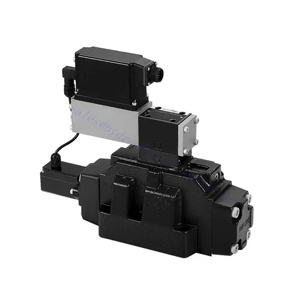
4WRLE Series Pilot Operated Proportional Directional Hydraulic Valve
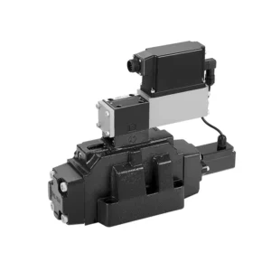

The 4WRLE series pilot-operated proportional directional hydraulic valve is a cutting-edge hydraulic component that revolutionizes fluid control in hydraulic systems. This valve combines pilot-operated technology with proportional directional control, offering precise flow regulation and exceptional efficiency.
The 4WRLE series pilot-operated proportional directional hydraulic valve elevates hydraulic control to new heights of precision and efficiency. With its pilot-operated technology and proportional directional control, this valve ensures accurate flow regulation, optimized energy consumption, and enhanced system performance. By following the recommended usage methods and maintenance guidelines, you can unleash the full potential of the 4WRLE series valve and achieve superior hydraulic control. Upgrade your hydraulic system today and experience the power of precision with the 4WRLE series pilot-operated proportional directional hydraulic valve.
4WRLE Series Pilot Operated Proportional Directional Hydraulic Valve Key Characteristics:
- Pilot Operated Technology:
- The 4WRLE series valve incorporates pilot-operated technology, allowing precise fluid flow control and pressure regulation.
- This technology enables efficient energy usage and reduces heat generation, resulting in improved overall system performance and reduced operating costs.
- Proportional Directional Control:
- With its proportional directional control capability, this valve provides accurate and balanced flow adjustment based on control signals.
- The proportional control allows for smooth and precise control of hydraulic actuators, enhancing system performance and minimizing wear and tear.
- Versatile Functionality:
- The 4WRLE series valve offers versatile control over fluid direction, making it suitable for a wide range of hydraulic applications.
- Whether it’s controlling cylinders, motors, or other hydraulic components, this valve ensures seamless activation and deactivation in different directions, enhancing system flexibility and adaptability.
- High Flow Capacity:
- Designed to handle high flow rates, the 4WRLE series valve delivers exceptional performance even in demanding applications.
- Its robust construction and optimized flow channels ensure reliable operation and consistent flow control, meeting the requirements of high-power hydraulic systems.
4WRLE Series Pilot Operated Proportional Directional Hydraulic Valve Parameter:
NG6
| General | |||||||
| Design | Spool valve, direct operated, with steel sleeve | ||||||
| Actuation | Proportional solenoid with position control, OBE | ||||||
| Connection type | Subplate mounting, porting pattern according to ISO 4401-03-02-0-05 | ||||||
| Installation position | Any | ||||||
| Ambient temperature range | ℃ | -20…+50 | |||||
| Weight | Kg | about 2.75 | |||||
| Maximum vibration resistance (test condition) | Max. 25 g, space vibration test in all directions (24h) | ||||||
| Hydraulic (measured at p=100bar, with HLP46 at ϑoil = 40℃ ±5℃) | |||||||
| Pressure fluid | Mineral oil (HL, HLP)to DIN 51 524 | ||||||
| Viscosity range | recommended | mm²/s | 20…100 | ||||
| max. permitted | mm²/s | 10…800 | |||||
| Pressure fluid temperature range | ℃ | -20 to +70 | |||||
| Maximum permitted degree of contamination of pressure fluid Purity class to ISO 4406 (c) | Class 18/16/13 | ||||||
| Rated flow (Δp = 35 bar per edge) | L/min | 2 | 4 | 12 | 24 | 40 | |
| Max. operating pressure | bar | Port A、B、P:315 | |||||
| Max. pressure | bar | Port T: 250 | |||||
| Leakage flow at 100 bar | Linear | cm³/min | <150 | <180 | <300 | <500 | <900; |
| Nonlinear | cm³/min | / | / | / | <300 | <450; | |
| Static/Dynamic | |||||||
| Hysteresis | % | ≤0.2 | |||||
| Actuating time for signal step 0 … 100% | ms | 10 | |||||
| Temperature drift | Zero shift < 1% at ΔT=40℃ | ||||||
| Zero compensation | Ex factory ±1% | ||||||
| Electric, control electronics integrated in the valve | |||||||
| Relative duty cycle | % | 100ED | |||||
| Degree of protection | IP65 | ||||||
| Connection | Plug-in connector 6P+PE, DIN 43563 | ||||||
| Supply voltage Terminal A Terminal B |
24VDCnom | ||||||
| min. 21VDC / max. 40VDC | |||||||
| 0V (ripple max. 2) | |||||||
| Fuse protection, external | AF | 2.5 | |||||
| nput, version “A1” Terminal D (UE) Terminal E |
Differential amplifier, Ri = 100 kΩ | ||||||
| 0…±10V | |||||||
| 0V | |||||||
| Input, version “F1” Terminal D (ID-E) Terminal E (ID-E) |
Load, Rsh = 200 Ω | ||||||
| 4…12…20mA | |||||||
| Current loop ID-E return | |||||||
| Test signal, version “A1” Terminal F (UTest) Terminal C |
LVDT | ||||||
| 0…±10V | |||||||
| Reference 0 V | |||||||
| Test signal, version “F1” Terminal F ( I F-C ) Terminal C ( I F-C ) |
LVDT signal 4 … (12) … 20 mA on external load 200 … 500 Ωmaximum | ||||||
| 4 … (12) … 20mA (output) | |||||||
| Current loop IF-C return | |||||||
| Adjustment | Calibrated before delivery, see characteristic curves | ||||||
NG10
| General | |||||
| Design | Spool valve, directly operated, with steel sleeve | ||||
| Actuation | Proportional solenoid with position control, OBE | ||||
| Connection type | Plate port, porting pattern (ISO 4401-05-04-0-05) | ||||
| Installation position | Any | ||||
| Circumstances temperature range | ℃ | -20…+50 | |||
| Weight | Kg | about 7.1 | |||
| Maximum vibration resistance (test condition) | Max. 25 g, space vibration test in all directions (24h) | ||||
| Hydraulic (measured with HLP 46, ϑoil =40℃ ±5℃) | |||||
| Pressure fluid | Hydraulic oil according to DIN 51524…535 | ||||
| Viscosity range | recommended | mm²/s | 20…100 | ||
| Max. permitted | mm²/s | 10…800 | |||
| Pressure fluid temperature range | ℃ | -20 to +70 | |||
| Max. admissible degree of contamination of the hydraulic fluid,cleanliness class according to ISO 4406 (c) | Class 18/16/13 | ||||
| Rated flow(Δp = 35 bar per edge) | L/min | 50 | 100 | ||
| Max. operating pressure | bar | Port P A B: 315 | |||
| Max. pressure | bar | Port T: 250 | |||
| Leakage flow at 100 bar | Linear | cm³/min | <1200 | <1500 | |
| Nonlinear | cm³/min | <600 | <600 | ||
| Static/Dynamic | |||||
| Hysteresis | % | ≤0.2 | |||
| Actuating time for signal step 0 … 100% | ms | 25 | |||
| Temperature drift | Zero shift < 1% at ΔT=40℃ | ||||
| Zero compensation | Ex factory ±1% | ||||
| Electric, control electronics integrated in the valve | |||||
| Relative duty cycle | % | 100ED | |||
| Degree of protection | IP65(with mating connector mounted and locked ) | ||||
| Connection | Mating connector 6P+PE, DIN 43563 | ||||
| Supply voltage Terminal A Terminal B |
24VDCnom | ||||
| min. 21VDC / max. 40VDC | |||||
| Ripple max. 2 VDC | |||||
| Fuse protection, external | AF | 2.5 | |||
| Input, version “A1” Terminal D (UE) Terminal E |
Differential amplifier, Ri = 100 kΩ | ||||
| 0…±10V | |||||
| 0V | |||||
| Input, version “F1” Terminal D (ID-E) Terminal E (ID-E) |
Load, Rsh = 200 | ||||
| 4…12…20mA | |||||
| Current loop ID-E return | |||||
| Test signal, version “A1” Terminal F (UTest) Terminal C |
LVDT | ||||
| 0…±10V | |||||
| Reference 0 V | |||||
| Test signal, version “F1” Terminal F ( I F-C ) Terminal C ( I F-C ) |
LVDT | ||||
| 4…20 mA output | |||||
| Current loop IF-C feedback | |||||
4WRLE Series Pilot Operated Proportional Directional Hydraulic Valve Advantages:
• Direct-acting servo solenoid valve with control piston and valve sleeve, with servo performance
• Single-side drive, optional, with power-off safety function
Control solenoid with built-in feedback and integrated amplifier board (OBE), factory preset
• Electrical connection 6P+PE signal input differential amplifier with interface, input optional A1: ±10V, or interface F1: 4…20mA (Rsh =200Ω)
• Panel mounting: the mounting surface complies with ISO 4401-03-02
Usage Method Of 4WRLE Series Pilot Operated Proportional Directional Hydraulic Valve:
- System Assessment:
- Evaluate your hydraulic system and define the specific flow and directional control requirements.
- Identify whether the 4WRLE series valve is compatible with your system based on factors such as flow capacity, pressure rating, and compatibility with your application.
- Valve Selection:
- Select the appropriate variant of the 4WRLE series valve based on your system parameters, flow requirements, and directional control needs.
- Consider factors such as maximum flow rate, pressure rating, response time, and environmental operating conditions.
- Installation:
- Follow the manufacturer’s installation instructions carefully to ensure proper alignment and secure valve mounting.
- Create leak-free connections and ensure correct flow direction alignment to guarantee optimal performance.
- Control Signal Integration:
- Connect the control signal wires of the valve to a suitable control device, such as a proportional amplifier or electronic control unit.
- Ensure proper wiring and compatibility between the valve and control device to achieve accurate and responsive control.
How To Hook Up A Hydraulic Flow Control Valve?
To hook up a hydraulic flow control valve, follow these steps:
- Identify Valve Type: Determine the specific type of flow control valve you are working with. Common types include needle valves, adjustable flow control valves, or pressure-compensated flow control valves. Ensure that the valve is suitable for your application and compatible with your hydraulic system.
- Gather Required Tools and Materials: Collect the necessary tools and materials, including appropriate hydraulic fittings, adapters, hoses, and wrenches.
- Prepare the Hydraulic System: Shut down the hydraulic system and relieve any pressure in the system by activating the relief valve or retracting any hydraulic cylinders. This step is crucial for safety.
- Identify Flow Direction: Identify the flow direction in your hydraulic system. Typically, the flow direction is indicated by arrows on the hydraulic components. Ensure that you understand the correct flow direction before proceeding.
- Locate Installation Point: Determine the optimal location to install the flow control valve in your hydraulic system. Consider factors such as accessibility, proximity to the actuator or hydraulic component, and ease of adjustment.
- Mount the Valve: Securely mount the flow control valve in the chosen location using appropriate brackets or clamps. Ensure the valve is positioned correctly, aligning the inlet and outlet ports with the flow direction.
- Connect the Inlet and Outlet Ports: Attach hydraulic hoses or tubing to the inlet and outlet ports of the flow control valve. Use suitable hydraulic fittings and adapters to create a leak-free connection. Tighten the connections using wrenches to ensure a secure fit, but avoid over-tightening.
- Adjust the Flow Control: Depending on the type of flow control valve, it may have adjustable features such as a needle valve or a flow control knob. Adjust the valve according to your desired flow rate or speed. Refer to the manufacturer’s instructions for specific adjustment procedures.
- Test the System: Once the flow control valve is installed and adjusted, slowly restore hydraulic system pressure. Test the system to ensure that the flow control valve is functioning correctly. Monitor the flow rate or speed of the hydraulic actuator to verify that it is within the desired range.
- Fine-tune and Monitor: Adjust the flow control valve to achieve the desired flow rate or speed. Regularly monitor the hydraulic system for leaks, pressure inconsistencies, or unusual behavior.
Capability & Capacity Of Factory:
(1) Assembly
We have a first-class independent research and development assembly platform. The hydraulic cylinder production workshop has four semi-automatic lifting cylinder assembly lines and one automatic tilt cylinder assembly line, with a designed annual production capacity of 1 million pieces. The special cylinder workshop is equipped with various specifications of a semi-automatic cleaning assembly system with a designed annual production capacity of 200,000 and equipped with famous CNC machining equipment, a machining center, a high-precision cylinder processing special equipment, a robot welding machine, an automatic cleaning machine, automatic cylinder assembly machine, and automatic painting production line. Existing critical equipment of more than 300 sets (sets). The optimal allocation and efficient use of equipment resources ensure the accuracy requirements of products and meet the high-quality needs of products.


(2) Machining
The machining shop is equipped with a customized inclined rail turning center, machining center, high-speed honing machine, welding robot, and other related equipment, which can handle the processing of cylinder tubes with a maximum inner diameter of 400mm and a maximum length of 6 meters.


(3) Welding


(4) Painting & coating
With small and medium-sized cylinder automatic water-based paint coating lines, to achieve automatic robot loading and unloading and automatic spraying, the design capacity of 4000 pieces per shift;
We also have a semi-automatic paint production line for large cylinders powered by a power chain, with 60 cases per shift design capacity.


(5) Testing
We have first-class inspection facilities and test beds to ensure that the performance of the cylinder meets the requirements.


We are one of the best hydraulic cylinder manufacturers. We can offer comprehensive hydraulic cylinders. We also provide corresponding agricultural gearboxes. We have exported our products to clients worldwide and earned a good reputation because of our superior product quality and after-sales service. We welcome customers at home and abroad to contact us to negotiate business, exchange information, and cooperate with us!