

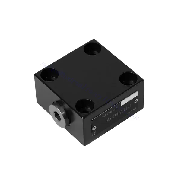
L-LFA Series Directional Control Hydraulic Valve
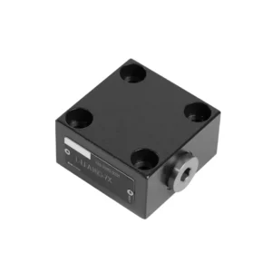

The L-LFA series directional control hydraulic valve is a cutting-edge component designed to deliver precise control and optimal performance in hydraulic systems. With its advanced features and robust construction, this valve provides reliable and efficient directional control for various applications.
The L-LFA series directional control hydraulic valve is a game-changer for hydraulic systems, offering precise directional control, versatility, and durability. By following the recommended usage methods and maintenance guidelines, you can harness the full potential of the L-LFA series valve and experience enhanced control, efficiency, and productivity in your hydraulic applications. Upgrade your hydraulic system today and unlock the advantages of precision and efficiency with the L-LFA series directional control hydraulic valve.
L-LFA Series Directional Control Hydraulic Valve Key Characteristics:
- Accurate Directional Control:
- The L-LFA series valve offers exceptional directional control, allowing precise and efficient management of fluid flow in hydraulic systems.
- This characteristic enables operators to direct hydraulic fluid to specific actuators or hydraulic components, facilitating smooth and controlled movement.
- Versatile Configuration Options:
- This valve is available in various configurations, including 2-way, 3-way, and 4-way options, ensuring compatibility with diverse hydraulic system requirements.
- The 2-way configuration facilitates simple on/off control, while the 3-way and 4-way configurations enable more complex functions such as cylinder extension, retraction, and bi-directional control.
- High-Performance Construction:
- The L-LFA series valve is engineered with high-quality materials and precision manufacturing techniques to ensure durability and longevity.
- Its robust construction allows it to withstand high pressures, temperature variations, and harsh operating conditions, ensuring reliable performance even in demanding environments.
- Quick Response Time:
- This valve boasts an impressive response time, enabling rapid and efficient fluid flow control within the hydraulic system.
- The quick response time facilitates precise and immediate adjustments, resulting in enhanced system performance and reduced energy consumption.
L-LFA Series Directional Control Hydraulic Valve Parameter:
| Maximum working pressure | Without directional valve | bar | 420 | |||||
| – Oil port A、B、X、Z1、Z2 | bar | 315; 350; 420(Depends on top-mounted directional valve) | ||||||
| – Oil port Y | bar | Equivalent to the return pressure of a top-mounted directional valve | ||||||
| Fluid | Mineral oil suitable for NBR and FKM seal | |||||||
| Phosphate ester for FKM seal | ||||||||
| Fluid temperature range | ℃ | -30 to +80(NBR seal) | ||||||
| -20 to +80(FKM seal) | ||||||||
| Viscosity range | mm2/s | 2.8 to 380 | ||||||
| Degree of contamination | Maximum permissible degree of fluid contamination: Class 9. NAS 1638 or 20/18/15 , ISO4406 | |||||||
L-LFA Series Directional Control Hydraulic Valve Advantages:
• Basic type D with remote control
• With stroke limiter H
• Built-in shuttle valve G
• Built-in directional seat valve R, RF
• Can be equipped with directional valve WE
Usage Method Of L-LFA Series Directional Control Hydraulic Valve:
- System Evaluation:
- Evaluate your hydraulic system and identify the specific directional control requirements.
- Determine whether the L-LFA series valve suits your system based on flow rates, pressure ratings, and compatibility with your application.
- Valve Selection:
- Select the appropriate variant of the L-LFA series valve based on your system parameters and directional control needs.
- Consider factors such as valve type (2-way, 3-way, or 4-way), flow capacity, pressure rating, and compatibility with your specific application.
- Installation:
- Follow the manufacturer’s installation instructions carefully to ensure proper alignment and secure valve mounting.
- Use compatible hydraulic fittings, adapters, and seals to establish leak-free connections. Tighten the connections adequately, avoiding overtightening that could damage the valve or fittings.
- System Integration:
- Connect the hydraulic lines to the appropriate ports of the L-LFA series valve, ensuring the correct flow direction.
- Verify that the valve is installed in the correct orientation, as indicated by the directional arrows on the valve body.
- Operation and Control:
- Familiarize yourself with the control mechanisms of the L-LFA Series Valve, such as levers, knobs, or solenoids.
- Ensure that the valve is actuated correctly and that the desired hydraulic flow is achieved based on the system requirements.
How To Install A Hydraulic Pressure Relief Valve?
Installing a hydraulic pressure relief valve is a crucial step in ensuring the safety and proper functioning of a hydraulic system. Here’s a step-by-step guide on how to install a hydraulic pressure relief valve:
- Identify the Valve: Determine the specific type and model of the hydraulic pressure relief valve you work with. Ensure it is suitable for your application and compatible with your hydraulic system requirements.
- Gather the Required Tools and Materials: Collect the necessary tools and materials, including appropriate hydraulic fittings, adapters, wrenches, Teflon tape (thread sealant), and a pressure gauge if needed. Refer to the manufacturer’s instructions for any specific tools or components required.
- Prepare the Hydraulic System: Shut down the hydraulic system and relieve pressure by activating the relief valve or retracting hydraulic cylinders. This step is crucial for safety and prevents accidental movement or hydraulic fluid release.
- Identify the Pressure Relief Point: Determine the optimal location to install the hydraulic pressure relief valve in your hydraulic system. It should be positioned downstream of the pump before any sensitive components to protect them from excessive pressure. Consult the hydraulic system schematic or seek professional advice if necessary.
- Mount the Valve: Securely mount the hydraulic pressure relief valve in the chosen location using appropriate brackets or clamps. Ensure the valve is positioned correctly, aligning the inlet and outlet ports with the flow direction. Follow the manufacturer’s instructions for specific mounting requirements.
- Connect the Inlet and Outlet Ports: Attach hydraulic hoses or tubing to the inlet and outlet ports of the relief valve. Use suitable hydraulic fittings and adapters to create a leak-free connection. Apply Teflon tape or thread sealant to the male threads of the fittings to ensure a secure and sealed connection. Tighten the connections using wrenches to avoid leaks, but be careful not to overtighten.
- Set the Pressure Relief Setting: Most hydraulic pressure relief valves come with an adjustable pressure relief setting. Adjust the relief valve to the desired pressure relief point using the manufacturer’s guidelines. Some valves may require a pressure gauge to accurately set the relief pressure. Install the pressure gauge temporarily, if needed, and adjust the relief valve until the desired pressure is achieved.
- Test the System: Once the hydraulic pressure relief valve is installed, slowly restore hydraulic system pressure. Monitor the pressure gauge or observe the system behavior to ensure that the relief valve functions correctly. The relief valve should open and divert excess pressure when it reaches the set point, preventing damage to the system.
- Monitor and Maintain: Regularly inspect the hydraulic pressure relief valve for any signs of leakage, damage, or reduced performance. Clean the valve and surrounding area to remove dirt and debris that may affect its operation. Follow the manufacturer’s recommended maintenance schedule and guidelines to ensure optimal performance and longevity.
Capability & Capacity Of Factory:
(1) Assembly
We have a first-class independent research and development assembly platform. The hydraulic cylinder production workshop has four semi-automatic lifting cylinder assembly lines and one automatic tilt cylinder assembly line, with a designed annual production capacity of 1 million pieces. The special cylinder workshop is equipped with various specifications of a semi-automatic cleaning assembly system with a designed annual production capacity of 200,000 and equipped with famous CNC machining equipment, a machining center, a high-precision cylinder processing special equipment, a robot welding machine, an automatic cleaning machine, automatic cylinder assembly machine, and automatic painting production line. Existing critical equipment of more than 300 sets (sets). The optimal allocation and efficient use of equipment resources ensure the accuracy requirements of products and meet the high-quality needs of products.


(2) Machining
The machining shop is equipped with a customized inclined rail turning center, machining center, high-speed honing machine, welding robot, and other related equipment, which can handle the processing of cylinder tubes with a maximum inner diameter of 400mm and a maximum length of 6 meters.


(3) Welding


(4) Painting & coating
With small and medium-sized cylinder automatic water-based paint coating lines, to achieve automatic robot loading and unloading and automatic spraying, the design capacity of 4000 pieces per shift;
We also have a semi-automatic paint production line for large cylinders powered by a power chain, with 60 cases per shift design capacity.


(5) Testing
We have first-class inspection facilities and test beds to ensure that the performance of the cylinder meets the requirements.


We are one of the best hydraulic cylinder manufacturers. We can offer comprehensive hydraulic cylinders. We also provide corresponding agricultural gearboxes. We have exported our products to clients worldwide and earned a good reputation because of our superior product quality and after-sales service. We welcome customers at home and abroad to contact us to negotiate business, exchange information, and cooperate with us!