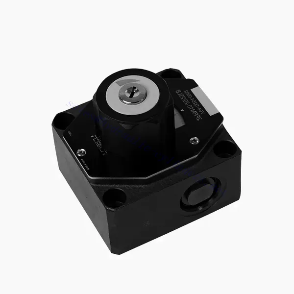
FRM Series Flow Control Hydraulic Valve
FRM Series Flow Control Hydraulic Valve
The FRM series flow control hydraulic valve is a cutting-edge hydraulic component designed to enhance the performance and control of hydraulic systems. With its advanced features and reliable functionality, this valve offers precise flow control and optimal efficiency.
The FRM series flow control hydraulic valve is a reliable and versatile solution for optimizing flow control in hydraulic systems. With its precise flow control capabilities, pressure and temperature stability, and durable construction, this valve offers enhanced performance and efficiency. Following the recommended usage methods and maintenance guidelines, operators can maximize the benefits of the FRM series flow control hydraulic valve, ensuring smooth operation and reliable flow control in their hydraulic applications. Upgrade your hydraulic system with this advanced valve and experience precision, efficiency, and productivity like never before.
FRM Series Flow Control Hydraulic Valve Key Characteristics:
- Flow Control Precision:
- The FRM series valve enables precise control over the flow rate of hydraulic fluids, allowing operators to fine-tune and regulate the speed of actuators.
- With its exceptional accuracy, this valve ensures consistent flow control, resulting in improved system performance and enhanced productivity.
- Aplicação versátil:
- The FRM series valve is highly versatile and compatible with various hydraulic systems, including industrial machinery, construction equipment, and mobile applications.
- Its adaptability makes it an ideal choice for a wide range of hydraulic setups, providing reliable and efficient flow control.
- Estabilidade à pressão e à temperatura:
- This hydraulic valve is designed to maintain consistent flow control even under varying pressure and temperature conditions.
- It ensures stable performance and prevents flow fluctuations, safeguarding the integrity and reliability of the hydraulic system.
- Construção durável:
- The FRM series valve is constructed with high-quality materials, ensuring durability and long-term reliability in demanding operating environments.
- Its robust design allows it to withstand high pressures, vibrations, and temperature extremes, providing a dependable solution for hydraulic applications.
FRM Series Flow Control Hydraulic Valve Parameter:
NG6
| Válvula de controle de fluxo | |||||||||||
| Pressão máxima de operação - Porta A | bar | 315 | |||||||||
| Diferencial de pressão ΔP para o fluxo de retorno livre B para A | Veja as curvas características. | ||||||||||
| diferencial de pressão mínimo | bar | 6 a 14 | |||||||||
| Estabilidade à pressão até P = 315 bar | % | ±2(Qmáx) | |||||||||
| Fluxo | Qmáx | L/min | 0.2 | 0.6 | 1.5 | 3 | 6 | 10 | 16 | 25 | 32 |
| Qmin para 100 bar | mL/min | 15 | 15 | 15 | 15 | 25 | 50 | 70 | 100 | 250 | |
| Qmin para 315 bar | 25 | 25 | 25 | 25 | 25 | 50 | 70 | 100 | 250 | ||
| Fluido | Óleo mineral, éster de fosfato | ||||||||||
| Faixa de temperatura do fluido | °C | – 20 a + 80 | |||||||||
| Faixa de viscosidade | mm²/s | 10 a 800 | |||||||||
| Grau de contaminação | Grau máximo permitido de contaminação do fluido: Classe 9. NAS 1638 ou 20/18/15, ISO4406 | ||||||||||
| Posição de instalação | Opcional | ||||||||||
| Circunstâncias faixa de temperatura | °C | -20 a +50 | |||||||||
| Peso | 2FRM6A…2FRM6B… | kg | cerca de 1,3 | ||||||||
| 2FRM6SB… | kg | cerca de 1,5 | |||||||||
| Retificador | |||||||||||
| Vazão nominal | bar | 320 | |||||||||
| Pressão máxima de operação | bar | até 210 | |||||||||
| pressão de rachadura | bar | 0.7 | |||||||||
| Peso | kg | cerca de 0,9 | |||||||||
NG5/10/16
| Válvula de controle de fluxo | ||||||||||||||||
| Pressão máxima de operação - Porta A | bar | 315 | ||||||||||||||
| Diferencial de pressão ΔP para o fluxo de retorno livre B para A | Veja as curvas características. | |||||||||||||||
| diferencial de pressão mínimo | bar | 6 a 14 | ||||||||||||||
| Fluido | Óleo mineral, éster de fosfato | |||||||||||||||
| Faixa de temperatura do fluido | °C | – 20 a + 80 | ||||||||||||||
| Faixa de viscosidade | mm²/s | 10 a 800 | ||||||||||||||
| Grau de contaminação | Grau máximo permitido de contaminação do fluido: Classe 9. NAS 1638 ou 20/18/15, ISO4406 | |||||||||||||||
| Tamanho | milímetros | 5 | 10 | 16 | ||||||||||||
| Taxa de fluxo máxima | L/min | 0.2 | 0.6 | 1.2 | 3 | 6 | 10 | 15 | 10 | 16 | 25 | 50 | 60 | 100 | 160 | |
| Fluxo de retorno de óleo B para A | mL/min | 0.5 | 0.5 | 0.6 | 0.9 | 1.8 | 3.6 | 6.7 | 2 | 2.5 | 3.5 | 6 | 2.8 | 4.3 | 7.3 | |
| Faixa de estabilidade de fluxo (%Qmax) (-20 a ±80℃) | ±5 | ±3 | ±2 | ±2 | ||||||||||||
| ±2 (P=210 bar) | ±2 (P=350 bar) | |||||||||||||||
| Pressão de trabalho | bar | 210 | 350 | |||||||||||||
| Redução mínima de pressão | bar | 3-5 | 6-8 | 3-7 | 5-12 | |||||||||||
| Peso | kg | 1.6 | 3.4 | 7.4 | ||||||||||||
| Retificador | ||||||||||||||||
| Fluido | Óleo mineral, éster de fosfato | |||||||||||||||
| Faixa de temperatura do fluido | -20 a +80 | |||||||||||||||
| Faixa de viscosidade | 10 a 800 | |||||||||||||||
| Grau de contaminação | Grau máximo permitido de contaminação do fluido: Classe 9. NAS 1638 ou 20/18/15, ISO4406 | |||||||||||||||
| Tamanho | 5 | 10 | 16 | |||||||||||||
| Fluxo | 15 | 50 | 160 | |||||||||||||
| Pressão de trabalho | 210 | 315 | 315 | |||||||||||||
| pressão de rachadura | 1 | 1.5 | 1.5 | |||||||||||||
| Peso | 0.6 | 3.2 | 9.3 | |||||||||||||
FRM Series Flow Control Hydraulic Valve Advantages:
• Montagem da placa de base (consulte o catálogo de produtos)
• Restritor de deslocamento com compensação de pressão, opcional
• Válvula unidirecional opcional
• Puxador com escala, com opção de travamento
Usage Method Of FRM Series Flow Control Hydraulic Valve:
- Avaliação do Sistema:
- Begin by assessing the hydraulic system’s requirements, including flow rates, pressure ranges, and desired flow control parameters.
- Determine if the FRM series valve suits the specific application based on its flow control capabilities.
- Seleção de válvulas:
- Select the appropriate variant of the FRM series valve based on the system parameters, desired flow rate, and compatibility with other system components.
- Considere fatores como capacidade máxima de vazão, pressão nominal e condições operacionais.
- Instalação:
- Follow the manufacturer’s installation instructions carefully, ensuring proper alignment and secure valve connections.
- Pay attention to the flow direction indicators, ensuring the correct positioning of the valve in the hydraulic system.
- Ajuste do controle de fluxo:
- Once installed, adjust the flow control settings of the valve according to the desired flow rate and system requirements.
- Fine-tune the valve to achieve the desired speed and performance of hydraulic actuators, optimizing the overall system operation.
How Hydraulic Valves Work?
Hydraulic valves are crucial in controlling the flow and direction of hydraulic fluid within a hydraulic system. They are essential components that enable the precise operation of various hydraulic machinery and equipment. Here’s a simplified explanation of how hydraulic valves work:
- Basics of Hydraulic Systems:
Hydraulic systems use fluid, typically oil, to transmit power and control the movement of mechanical components. These systems consist of a hydraulic pump that pressurizes the liquid, a series of valves that control the flow and direction of the fluid, and hydraulic actuators (such as cylinders or motors) that convert the fluid energy into mechanical force or motion. - Valve Types:
There are various hydraulic valves, including directional control valves, pressure control valves, flow control valves, and check valves. Each valve type serves a specific purpose in regulating fluid flow, pressure, or direction. - Válvulas de controle direcional:
Directional control valves determine the path through which the hydraulic fluid flows. They have multiple positions (such as open, closed, or partially open) and multiple ports to direct the fluid to different sections of the hydraulic system. - Valve Components:
Hydraulic valves typically consist of a valve body, which contains internal passages and channels, and a movable valve element or spool that slides within the valve body. The spool has different lands or ports that align with the internal passages to control fluid flow. - Spool Movement:
The position of the spool within the valve body determines the flow path and, consequently, the direction of fluid flow. The spool can be actuated by various means, such as mechanical linkages, solenoids, or pilot pressure. - Válvulas de controle de pressão:
Pressure control valves regulate the pressure of the hydraulic fluid within the system. They can maintain a specific pressure level by allowing excess fluid to return to the reservoir or blocking flow until a desired pressure is reached. - Válvulas de controle de fluxo:
Flow control valves manage the rate of fluid flow within the hydraulic system. They can be used to control the speed of hydraulic actuators or to limit the flow rate to specific sections of the system. - Check Valves:
Check valves, or one-way valves, allow fluid flow in one direction and prevent backflow. They ensure that the fluid moves in the desired direction and avoid any undesired pressure drops or loss of hydraulic force. - Atuação da válvula:
Hydraulic valves can be manually operated, mechanically actuated, or controlled electronically. Levers or knobs directly handle manual valves, while mechanical and electronic actuators enable automated control of valve positions based on system requirements. - System Control:
By combining different types of hydraulic valves and controlling their positions or actuation, the hydraulic system’s overall function can be precisely regulated. This enables operators to control the movement, speed, force, and direction of hydraulic actuators, allowing for precise and efficient operation of hydraulic machinery.
Aptidão e capacidade da fábrica:
(1) Montagem
Temos uma plataforma de montagem de pesquisa e desenvolvimento independente de primeira classe. A oficina de produção de cilindros hidráulicos tem quatro linhas de montagem semiautomáticas de cilindros de elevação e uma linha de montagem automática de cilindros de inclinação, com uma capacidade de produção anual projetada de 1 milhão de peças. A oficina de cilindros especiais é equipada com várias especificações de um sistema de montagem de limpeza semiautomática com uma capacidade de produção anual projetada de 200.000 peças e equipada com famosos equipamentos de usinagem CNC, um centro de usinagem, um equipamento especial de processamento de cilindros de alta precisão, uma máquina de solda robotizada, uma máquina de limpeza automática, uma máquina de montagem automática de cilindros e uma linha de produção de pintura automática. O equipamento crítico existente é de mais de 300 conjuntos (conjuntos). A alocação ideal e o uso eficiente dos recursos do equipamento garantem os requisitos de precisão dos produtos e atendem às necessidades de alta qualidade dos produtos.


(2) Usinagem
A oficina de usinagem é equipada com um centro de torneamento de trilho inclinado personalizado, um centro de usinagem, uma máquina de brunimento de alta velocidade, um robô de soldagem e outros equipamentos relacionados, que podem lidar com o processamento de tubos de cilindros com diâmetro interno máximo de 400 mm e comprimento máximo de 6 metros.

(3) Soldagem

(4) Pintura e revestimento
Com linhas de revestimento de tinta à base de água automáticas de cilindros de pequeno e médio porte, para obter carregamento e descarregamento automáticos de robôs e pulverização automática, a capacidade projetada é de 4.000 peças por turno;
Também temos uma linha de produção de tinta semiautomática para cilindros grandes, acionada por uma corrente elétrica, com capacidade de projeto de 60 caixas por turno.


(5) Testes
Temos instalações de inspeção e bancos de teste de primeira classe para garantir que o desempenho do cilindro atenda aos requisitos.

Somos um dos melhores fabricantes de cilindros hidráulicos. Oferecemos cilindros hidráulicos completos. Também fornecemos os correspondentes caixas de câmbio agrícolas. Exportamos nossos produtos para clientes em todo o mundo e conquistamos uma boa reputação devido à qualidade superior de nossos produtos e ao serviço pós-venda. Convidamos clientes nacionais e estrangeiros a entrar em contato conosco para negociar negócios, trocar informações e cooperar conosco!


