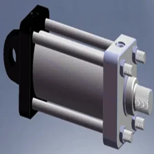
30SD08-30 Solenoid Directional Valve
30SD08-30 Solenoid Directional Valve
Experience unparalleled precision and control in your hydraulic system with the 30SD08-30 solenoid directional valve. This high-performance valve is designed to meet the demands of industrial applications, offering seamless fluid flow management and reliable operation.
The 30SD08-30 solenoid directional valve is a game-changer for hydraulic systems, offering precise control, high flow capacity, and rapid response time. With its durability and reliability, this valve guarantees optimal performance and efficiency. By following the recommended usage methods and maintenance guidelines, you can harness the full potential of the 30SD08-30 solenoid directional valve, achieving seamless control, increased productivity, and improved overall performance. Upgrade your hydraulic system today with the 30SD08-30 solenoid directional valve and experience the precision and reliability it brings to your operations.
30SD08-26 Solenoid Directional Valve Characteristics:
- Accurate Fluid Flow Control:
- The 30SD08-30 solenoid directional valve provides precise control over fluid flow, ensuring accurate and reliable operation of your hydraulic system.
- Experience seamless adjustments in flow rates, facilitating optimal performance in various industrial applications.
- Alta capacidade de fluxo:
- With its high flow capacity design, the 30SD08-30 solenoid directional valve can handle substantial fluid volumes efficiently.
- This feature enables smooth and reliable operation, even in applications that require high flow rates, ensuring optimal system performance.
- Tempo de resposta rápido:
- Equipped with advanced solenoid technology, the 30SD08-30 solenoid directional valve boasts a rapid response time.
- Experience swift and accurate adjustments in fluid flow direction, allowing for enhanced system efficiency and precise control.
- Durabilidade e confiabilidade:
- Built to withstand demanding operating conditions, the 30SD08-30 solenoid directional valve features a robust construction.
- Its durable materials and reliable design minimize downtime, reduce maintenance requirements, and ensure long-lasting performance.
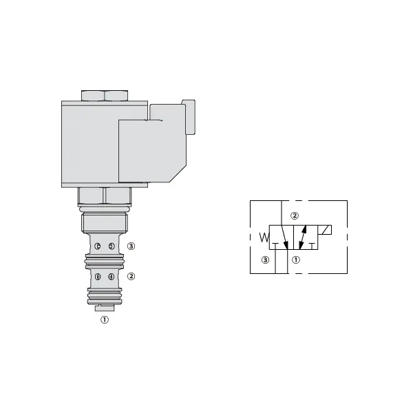
30SD08-25 Solenoid Directional Valve Parameter:
| Pressão nominal | 207 bar (3000 psi) |
| Pico de fluxo | Veja o gráfico de desempenho |
| Fluido | À base de minerais ou sintéticos com propriedades lubrificantes |
| Faixa de temperatura do fluido ℃ | -54 a 107 ℃ (Vedantes de poliuretano) |
| -40 a 100 ℃ (vedações Buna N) | |
| -26 a 204 ℃ (vedações de fluorocarbono) | |
| Faixa de viscosidade | 7,4 a 420 mm2/s |
| Grau de contaminação | O nível mínimo de poluição é ISO4406 nível 20/18/14, e o nível 17/15/13 é recomendado para prolongar a vida útil |
| Vazamento interno | Port 3 (De-energized): ≤ 82 mL/min@207bar |
| Port 1 (Energized): ≤ 164 mL/min@207bar | |
| Cavidade | VC08-3(Cavity variation ‘A’, see technical reference) |
| Classificação de serviço da bobina | Contínuo de 85% a 115% de tensão nominal |
| Consumo inicial de corrente da bobina a 20℃ | 1,4 A a 12 VCC; 0,7 A a 24 VCC |
| Tensão mínima de entrada | 85% de nominal a 207 bar (3000 psi) |
30SD08-25 Solenoid Directional Valve Advantages:
• Bobina nominal para serviço contínuo
• Construção eficiente de armadura úmida
• Os cartuchos são intercambiáveis em termos de voltagem
• Bobinas elétricas à prova d'água opcionais com classificação até IP69K
• Peças temperadas para longa vida útil
Usage Method Of 30SD08-25 Solenoid Directional Valve:
- Avaliação do Sistema:
- Begin by assessing the specific requirements of your hydraulic system, considering flow rates, pressure levels, and system dynamics.
- Evaluate if the 30SD08-30 Solenoid Directional Valve aligns with your system’s needs, taking into account its precision, flow capacity, and compatibility with other components.
- Seleção de válvulas:
- Select the appropriate variant of the 30SD08-30 solenoid directional valve based on your system parameters and performance requirements.
- Consider factors such as flow capacity, pressure ratings, and compatibility to ensure seamless integration and optimal functionality.
- Instalação:
- Follow the manufacturer’s installation instructions carefully to ensure proper placement and secure mounting of the valve.
- Position the valve correctly within the hydraulic system, considering fluid flow direction and accessibility for maintenance purposes.
- Conexões elétricas:
- Connect the solenoid valve to the designated power source according to the manufacturer’s specifications.
- Ensure that the electrical connections are secure, adhering to safety standards and guidelines.
Como conectar uma válvula de controle de fluxo hidráulico?
Para conectar uma válvula de controle de fluxo hidráulico, siga estes passos:
- Identificar o tipo de válvula: Determine o tipo específico de válvula de controle de fluxo com a qual você está trabalhando. Os tipos mais comuns incluem válvulas de agulha, válvulas de controle de fluxo ajustáveis ou válvulas de controle de fluxo com compensação de pressão. Certifique-se de que a válvula seja adequada para sua aplicação e compatível com seu sistema hidráulico.
- Reúna as ferramentas e materiais necessários: Reúna as ferramentas e os materiais necessários, incluindo conexões hidráulicas, adaptadores, mangueiras e chaves apropriadas.
- Prepare o sistema hidráulico: Desligue o sistema hidráulico e alivie qualquer pressão no sistema acionando a válvula de alívio ou retraindo os cilindros hidráulicos. Esta etapa é crucial para a segurança.
- Identificar a direção do fluxo: Identifique o sentido do fluxo no seu sistema hidráulico. Normalmente, o sentido do fluxo é indicado por setas nos componentes hidráulicos. Certifique-se de compreender o sentido correto do fluxo antes de prosseguir.
- Localizar ponto de instalação: Determine a localização ideal para instalar a válvula de controle de fluxo em seu sistema hidráulico. Considere fatores como acessibilidade, proximidade ao atuador ou componente hidráulico e facilidade de ajuste.
- Monte a válvula: Monte a válvula de controle de fluxo com segurança no local escolhido, utilizando suportes ou braçadeiras apropriadas. Certifique-se de que a válvula esteja posicionada corretamente, alinhando as portas de entrada e saída com a direção do fluxo.
- Conecte as portas de entrada e saída: Conecte as mangueiras ou tubos hidráulicos às portas de entrada e saída da válvula de controle de fluxo. Utilize conexões e adaptadores hidráulicos adequados para garantir uma conexão sem vazamentos. Aperte as conexões com chaves para assegurar uma fixação segura, mas evite apertá-las em excesso.
- Ajuste o controle de fluxo: Dependendo do tipo de válvula de controle de fluxo, ela pode ter recursos ajustáveis, como uma válvula de agulha ou um botão de controle de fluxo. Ajuste a válvula de acordo com a vazão ou velocidade desejada. Consulte as instruções do fabricante para obter os procedimentos de ajuste específicos.
- Teste o sistema: Após a instalação e o ajuste da válvula de controle de fluxo, restabeleça lentamente a pressão do sistema hidráulico. Teste o sistema para garantir que a válvula de controle de fluxo esteja funcionando corretamente. Monitore a vazão ou a velocidade do atuador hidráulico para verificar se está dentro da faixa desejada.
- Ajuste fino e monitoramento: Ajuste a válvula de controle de fluxo para obter a vazão ou velocidade desejada. Monitore regularmente o sistema hidráulico para detectar vazamentos, inconsistências de pressão ou comportamentos anormais.
Aptidão e capacidade da fábrica:
(1) Montagem
Temos uma plataforma de montagem de pesquisa e desenvolvimento independente de primeira classe. A oficina de produção de cilindros hidráulicos tem quatro linhas de montagem semiautomáticas de cilindros de elevação e uma linha de montagem automática de cilindros de inclinação, com uma capacidade de produção anual projetada de 1 milhão de peças. A oficina de cilindros especiais é equipada com várias especificações de um sistema de montagem de limpeza semiautomática com uma capacidade de produção anual projetada de 200.000 peças e equipada com famosos equipamentos de usinagem CNC, um centro de usinagem, um equipamento especial de processamento de cilindros de alta precisão, uma máquina de solda robotizada, uma máquina de limpeza automática, uma máquina de montagem automática de cilindros e uma linha de produção de pintura automática. O equipamento crítico existente é de mais de 300 conjuntos (conjuntos). A alocação ideal e o uso eficiente dos recursos do equipamento garantem os requisitos de precisão dos produtos e atendem às necessidades de alta qualidade dos produtos.


(2) Usinagem
A oficina de usinagem é equipada com um centro de torneamento de trilho inclinado personalizado, um centro de usinagem, uma máquina de brunimento de alta velocidade, um robô de soldagem e outros equipamentos relacionados, que podem lidar com o processamento de tubos de cilindros com diâmetro interno máximo de 400 mm e comprimento máximo de 6 metros.

(3) Soldagem

(4) Pintura e revestimento
Com linhas de revestimento de tinta à base de água automáticas de cilindros de pequeno e médio porte, para obter carregamento e descarregamento automáticos de robôs e pulverização automática, a capacidade projetada é de 4.000 peças por turno;
Também temos uma linha de produção de tinta semiautomática para cilindros grandes, acionada por uma corrente elétrica, com capacidade de projeto de 60 caixas por turno.


(5) Testes
Temos instalações de inspeção e bancos de teste de primeira classe para garantir que o desempenho do cilindro atenda aos requisitos.

Somos um dos melhores fabricantes de cilindros hidráulicos. Oferecemos cilindros hidráulicos completos. Também fornecemos os correspondentes caixas de câmbio agrícolas. Exportamos nossos produtos para clientes em todo o mundo e conquistamos uma boa reputação devido à qualidade superior de nossos produtos e ao serviço pós-venda. Convidamos clientes nacionais e estrangeiros a entrar em contato conosco para negociar negócios, trocar informações e cooperar conosco!